Difference between revisions of "8051 Development Board Setup"
m (Sandeep moved page 8051 ToolsSetup to 4.8051 Hardware and Software Setup) |
|||
| (24 intermediate revisions by 2 users not shown) | |||
| Line 1: | Line 1: | ||
[[Category:8051_tutorials]] | [[Category:8051_tutorials]] | ||
| − | + | The Explore Ultra 8051 Kit comes with all the things required, not just for this experiment but for the entire series. The base board is fully open, no peripheral is directly connected to the MCU breakout board. You may connect any peripheral to any port/pin you wish. The kit is fully open source, you may use the schematics, the design files and all of the source code and build something cool on your own. And when you do that do not forget to share with us what you've done. We would be happy to see you building something cool. | |
| − | + | [[File:0ultra 8051.png]] | |
| − | + | ||
| − | + | ||
| − | + | The story of the Ultra Kit does not end here, we have even made the code libraries for all major 8-bit microcontrollers modular. It means you can simple upgrade or even switch your project to a different microcontroller/architecture without changing your application code. The kit ships with all the additional stuff mentioned below to get you started; kickstart your embedded development. What are you waiting for? | |
| − | + | ||
| − | + | ||
| − | + | ||
| − | + | Kit Contents: | |
| − | + | Explore ULTRA PIC Development Board with following Modules, ICs and Interfaces: | |
| − | + | #USB Communication with CP2102 | |
| − | + | #Eight 5mm LEDs | |
| + | #Eight Switches in DIP package | ||
| + | #LCD 16x2 | ||
| + | #Four Seven Segment Displays | ||
| + | #ADC 0808 with 555 timer for sampling frequency | ||
| + | #POT for ADC | ||
| + | #Light Sensor(LDR). | ||
| + | #Temperature sensor(LM35). | ||
| + | #Two Relays for Switching AC devices. | ||
| + | #4x4 Keypad. | ||
| + | #L293D Motor Driver for DC and Stepper Motors. | ||
| + | #DS1307 based Real Time Clock. | ||
| + | #AT2404 EEPROM. | ||
| + | #USB cable. | ||
| + | #Power Adapter | ||
| + | #Single wire female connectors. <br><br> | ||
| − | + | =Supported Controllers= | |
| − | + | {| class="table table-striped table-hover table-condensed table-bordered" | |
| + | |-class="info" | ||
| + | !Controller || Flashing Software || External Programmer || Comments | ||
| + | |- | ||
| + | |At89s52|| XploreFlash/ProgIsp || UsbAsp Programmer ||IC is cheap and easily available but needs external programmer | ||
| + | |-class="active" | ||
| + | |P89v519d2|| Flash Magic || Not required, uses on board USB ||NXP has stopped manufacturing the IC and only the stock items are being sold. | ||
| + | |- | ||
| + | |SST8951RD2|| Easy ISP || Not required, uses on board USB ||IC is good but the programming software is not stable, doesn't save the configuration, needs manual reset and many other problems. | ||
| + | |-class="active" | ||
| + | |w78e052d || Nuvoton ISP || Not required, uses on board USB ||IC is cheap and good GUI for flasing the code. FLashing hex file takes less time compared to all | ||
| + | |}<br><br> | ||
| − | |||
| − | |||
| − | + | =Driver Installation= | |
| − | [[ | + | *Check [[Cp2102 Usb-to-Serial Driver Installation|this tutorial]] for Usb2Serial Driver Installation. |
| − | + | =Software Setup= | |
| − | [[File | + | *Compiler Installation: Download and Install the Keil software [https://github.com/ExploreEmbedded/Keil4_For_8051/archive/master.zip from this link]. |
| + | *Check [[Keil Setup For 8051|this tutorial]] for setting up the Keil project to generate the .hex file. | ||
| + | *Check [[Xplore Flash for At89s52|this tutorial]] for Uploading Hex File Using Xplore Flash for AT89S52. | ||
| + | *Check [[NuvoTon ISP For 8051|this tutorial]] for Uploading Hex File Using Nuvoton ISP.. | ||
| − | + | =Complete Board Test= | |
| − | + | <font color="red"> The board is shipped with test software loaded in the controller. Connect the board to the System, Open the [https://github.com/ExploreEmbedded/terminalSoftware/archive/master.zip Serial Terminal], Set the baud rate to 9600 and reset the Controller. Below Test menu will appear, Select the required peripheral and follow the below procedure to test all the peripherals.</font> | |
| − | + | [[File:8051 TestMenu.png ]] | |
| − | [[File: | + | |
| − | ' | + | ===GPIO Test=== |
| − | [[File: | + | Connect the LED's, Buzzer and Relays to any of the port pins and observe the Led Blink, Buzzer-Beep, and Relay-Chattering . |
| + | <b>*Note:</b>The Rx,Tx pins will not blink as they are controlled by CP2102(Usb2Serial). | ||
| + | [[File:GpioTest.png]]<br> | ||
| + | [[File:8051 GPIO Testing.png]]<br><br> | ||
| − | |||
| − | |||
| − | |||
| − | + | ===LCD 8-bit Test=== | |
| − | [[File: | + | Below table shows the LCD 8-bit pin connection. |
| + | {| class="table table-striped table-hover table-condensed table-bordered" | ||
| + | |-class="info" | ||
| + | !RS || RW || EN || D0 || D1 || D2 || D3 || D4 || D5 || D6 || D7 | ||
| + | |- | ||
| + | |P0_0 || P0_1 || P0_2 || P2_0 || P2_1 || P2_2 || P2_3 || P2_4 || P2_5 || P2_6 || P2_7 | ||
| + | |} | ||
| + | [[File:Lcd8bit.png]]<br> | ||
| + | [[File:8051 LCD 8-bit Test.png]]<br><br> | ||
| − | |||
| − | |||
| − | |||
| − | |||
| − | + | ===LCD 4-bit Test=== | |
| − | [[File: | + | Below table shows the LCD 4-bit pin connection. |
| + | {| class="table table-striped table-hover table-condensed table-bordered" | ||
| + | |-class="info" | ||
| + | !RS || RW || EN || D0 || D1 || D2 || D3 || D4 || D5 || D6 || D7 | ||
| + | |- | ||
| + | |P0_0 || P0_1 || P0_2 || P_NC || P_NC || P_NC || P_NC || P2_4 || P2_5 || P2_6 || P2_7 | ||
| + | |} | ||
| + | *P_NC: Pin Not Connected | ||
| + | [[File:Lcd4bitTestCode.png]]<br> | ||
| + | [[File:8051 LCD 4-bit Test.png]]<br><br> | ||
| − | + | ===Seven Segment Test=== | |
| − | [[File: | + | Below table shows the Seven Segment Connection. |
| − | [[File: | + | {| class="table table-striped table-hover table-condensed table-bordered" |
| + | |-class="info" | ||
| + | !Seg1|| Seg2 || Seg3 || Seg4 || a || b || c || d || e || f || g || h | ||
| + | |- | ||
| + | |P0_0 || P0_1 || P0_2 || P0_3 || P2_0 || P2_1 || P2_2 || P2_3 || P2_4 || P2_5 || P2_6 || P2_7 | ||
| + | |} | ||
| + | [[File:SevenSegmentTest.png]]<br> | ||
| + | [[File:8051 SevenSegment.png]]<br><br> | ||
| − | + | ===RTC Test=== | |
| − | [[File: | + | The DS1307 RTC pins are connected to P0 (SCL-P0.6,SDA-P0.7). |
| + | [[File:RtcEeprom.png]]<br> | ||
| + | [[File:8051 RTC Testing.png]]<br><br> | ||
| − | + | ===EEprom Test=== | |
| − | [[File: | + | (A-Z) is written to EEPROM and then read it back. Same is transmitted on UART.<br> |
| + | The AT24cxx Eeprom pins are connected to P0 (SCL-P0.6,SDA-P0.7). | ||
| + | [[File:RtcEeprom.png]]<br> | ||
| + | [[File:8051 Eeprom Test.png]]<br><br> | ||
| − | + | ===Adc Test=== | |
| − | [[File: | + | Ultra Board has a Pot, LDR and a temperature sensor. ADC values from these sensors is read and transmitted on UART. Below table shows the sensor pin connection. |
| + | {| class="table table-striped table-hover table-condensed table-bordered" | ||
| + | |-class="info" | ||
| + | !ADC DataBus(D0:D7)|| A || B || C || ALE || START || EOC || OE | ||
| + | |- | ||
| + | |P2(P2_0:P2_7) || P1_0 || P1_1 || P1_2 || P1_3 || P1_4 || P1_5 || P1_6 | ||
| + | |} | ||
| + | [[File:Adc0809 Interafce.png]] | ||
| + | [[File:8051 ADC Test.png]]<br><br> | ||
| − | + | ===Keypad Test=== | |
| − | [[File: | + | Below table shows the hex keypad Row-Col pin connection. |
| + | {| class="table table-striped table-hover table-condensed table-bordered" | ||
| + | |-class="info" | ||
| + | !R1 || R2 || R3 || R4 || C1 || C2 || C3 || C4 | ||
| + | |- | ||
| + | |P2_0 || P2_1 || P2_2 || P2_3 || P2_4 || P2_5 || P2_6 || P2_7 | ||
| + | |} | ||
| + | [[File:KeyPad.png]]<br> | ||
| + | [[File:8051 Hex Keypad.png]]<br><br> | ||
| − | + | =Downloads= | |
| − | [ | + | *Download the design files and sample codes from [https://github.com/ExploreEmbedded/8051_DevelopmentBoard this link] |
| − | + | *Download the Keil software from [https://github.com/ExploreEmbedded/Keil4_For_8051/archive/master.zip this link] | |
| − | |||
| − | |||
| − | + | Have an opinion, suggestion , question or feedback about the article let it out here! | |
| − | + | ||
| − | + | ||
| − | + | ||
| − | + | ||
| − | + | ||
| − | + | ||
| − | + | ||
| − | + | ||
| − | + | ||
| − | + | ||
| − | + | ||
| − | + | ||
| − | + | ||
| − | + | ||
| − | + | ||
| − | + | ||
| − | + | ||
| − | + | ||
| − | + | ||
| − | + | ||
| − | + | ||
| − | + | ||
| − | + | ||
| − | + | ||
| − | + | ||
| − | + | ||
| − | + | ||
| − | + | ||
| − | + | ||
| − | + | ||
| − | + | ||
| − | + | ||
| − | + | ||
| − | + | ||
| − | + | ||
| − | + | ||
| − | + | ||
| − | + | ||
| − | + | ||
| − | + | ||
| − | + | ||
| − | + | ||
| − | + | ||
| − | + | ||
| − | + | ||
| − | + | ||
| − | + | ||
| − | + | ||
| − | + | ||
| − | + | ||
| − | + | ||
| − | + | ||
| − | + | ||
| − | + | ||
| − | + | ||
| − | + | ||
{{DISQUS}} | {{DISQUS}} | ||
Latest revision as of 13:00, 22 November 2016
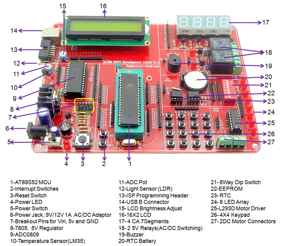
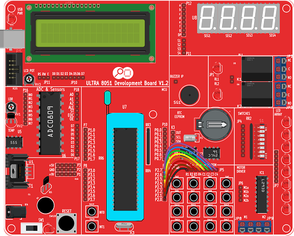
The Explore Ultra 8051 Kit comes with all the things required, not just for this experiment but for the entire series. The base board is fully open, no peripheral is directly connected to the MCU breakout board. You may connect any peripheral to any port/pin you wish. The kit is fully open source, you may use the schematics, the design files and all of the source code and build something cool on your own. And when you do that do not forget to share with us what you've done. We would be happy to see you building something cool.
The story of the Ultra Kit does not end here, we have even made the code libraries for all major 8-bit microcontrollers modular. It means you can simple upgrade or even switch your project to a different microcontroller/architecture without changing your application code. The kit ships with all the additional stuff mentioned below to get you started; kickstart your embedded development. What are you waiting for?
Kit Contents: Explore ULTRA PIC Development Board with following Modules, ICs and Interfaces:
- USB Communication with CP2102
- Eight 5mm LEDs
- Eight Switches in DIP package
- LCD 16x2
- Four Seven Segment Displays
- ADC 0808 with 555 timer for sampling frequency
- POT for ADC
- Light Sensor(LDR).
- Temperature sensor(LM35).
- Two Relays for Switching AC devices.
- 4x4 Keypad.
- L293D Motor Driver for DC and Stepper Motors.
- DS1307 based Real Time Clock.
- AT2404 EEPROM.
- USB cable.
- Power Adapter
- Single wire female connectors.
Contents
Supported Controllers
| Controller | Flashing Software | External Programmer | Comments |
|---|---|---|---|
| At89s52 | XploreFlash/ProgIsp | UsbAsp Programmer | IC is cheap and easily available but needs external programmer |
| P89v519d2 | Flash Magic | Not required, uses on board USB | NXP has stopped manufacturing the IC and only the stock items are being sold. |
| SST8951RD2 | Easy ISP | Not required, uses on board USB | IC is good but the programming software is not stable, doesn't save the configuration, needs manual reset and many other problems. |
| w78e052d | Nuvoton ISP | Not required, uses on board USB | IC is cheap and good GUI for flasing the code. FLashing hex file takes less time compared to all |
Driver Installation
- Check this tutorial for Usb2Serial Driver Installation.
Software Setup
- Compiler Installation: Download and Install the Keil software from this link.
- Check this tutorial for setting up the Keil project to generate the .hex file.
- Check this tutorial for Uploading Hex File Using Xplore Flash for AT89S52.
- Check this tutorial for Uploading Hex File Using Nuvoton ISP..
Complete Board Test
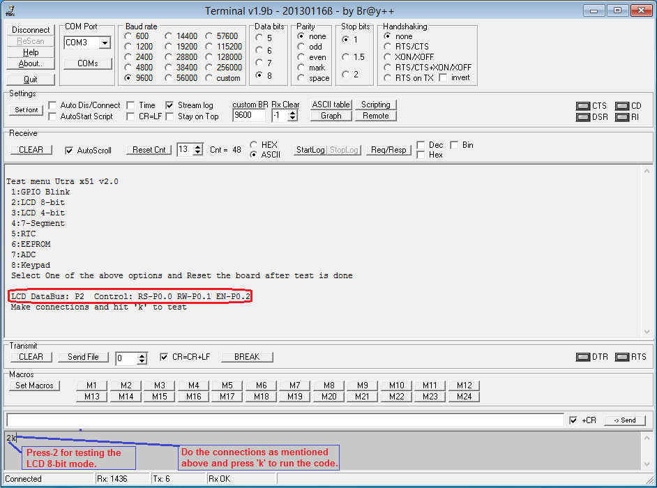
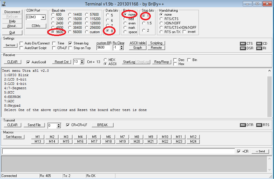
The board is shipped with test software loaded in the controller. Connect the board to the System, Open the Serial Terminal, Set the baud rate to 9600 and reset the Controller. Below Test menu will appear, Select the required peripheral and follow the below procedure to test all the peripherals.
GPIO Test
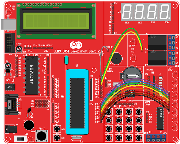
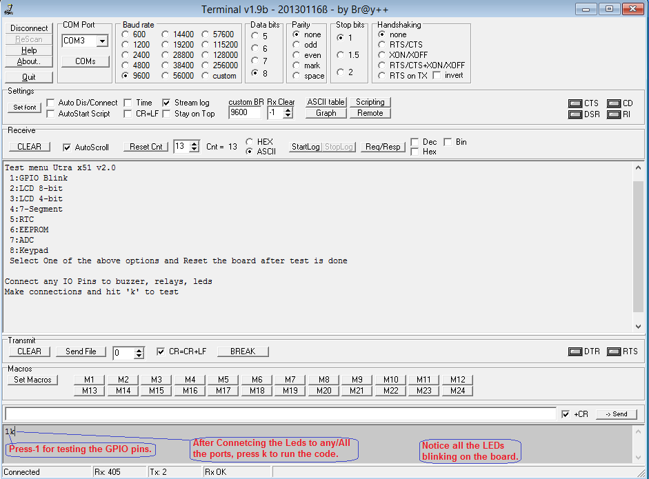
Connect the LED's, Buzzer and Relays to any of the port pins and observe the Led Blink, Buzzer-Beep, and Relay-Chattering .
*Note:The Rx,Tx pins will not blink as they are controlled by CP2102(Usb2Serial).
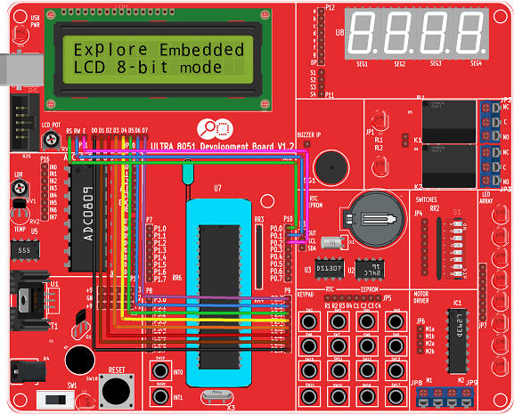
LCD 8-bit Test
Below table shows the LCD 8-bit pin connection.
| RS | RW | EN | D0 | D1 | D2 | D3 | D4 | D5 | D6 | D7 |
|---|---|---|---|---|---|---|---|---|---|---|
| P0_0 | P0_1 | P0_2 | P2_0 | P2_1 | P2_2 | P2_3 | P2_4 | P2_5 | P2_6 | P2_7 |
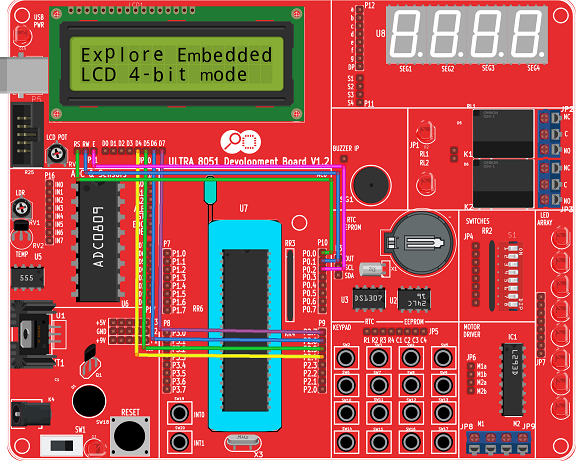
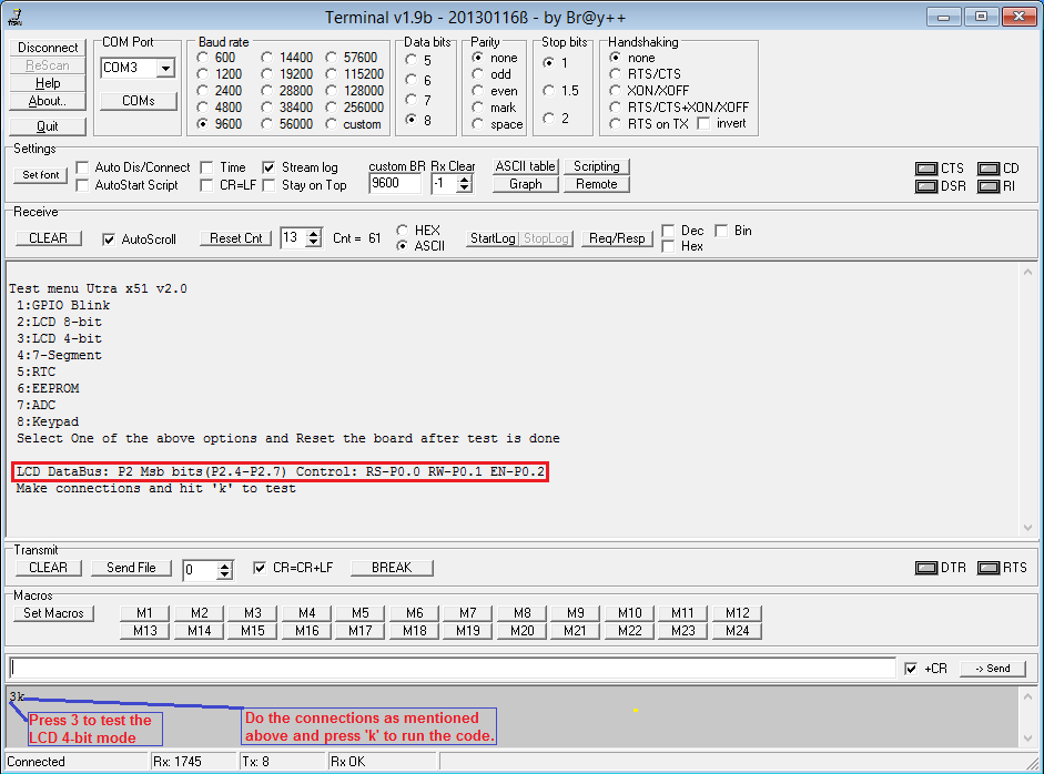
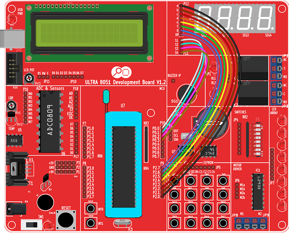
LCD 4-bit Test
Below table shows the LCD 4-bit pin connection.
| RS | RW | EN | D0 | D1 | D2 | D3 | D4 | D5 | D6 | D7 |
|---|---|---|---|---|---|---|---|---|---|---|
| P0_0 | P0_1 | P0_2 | P_NC | P_NC | P_NC | P_NC | P2_4 | P2_5 | P2_6 | P2_7 |
- P_NC: Pin Not Connected
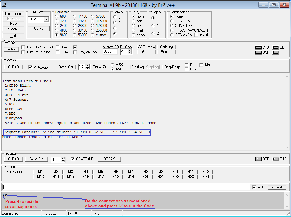
Seven Segment Test
Below table shows the Seven Segment Connection.
| Seg1 | Seg2 | Seg3 | Seg4 | a | b | c | d | e | f | g | h |
|---|---|---|---|---|---|---|---|---|---|---|---|
| P0_0 | P0_1 | P0_2 | P0_3 | P2_0 | P2_1 | P2_2 | P2_3 | P2_4 | P2_5 | P2_6 | P2_7 |
RTC Test
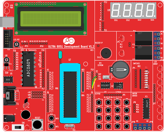
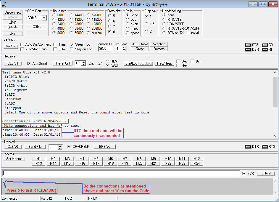
The DS1307 RTC pins are connected to P0 (SCL-P0.6,SDA-P0.7).
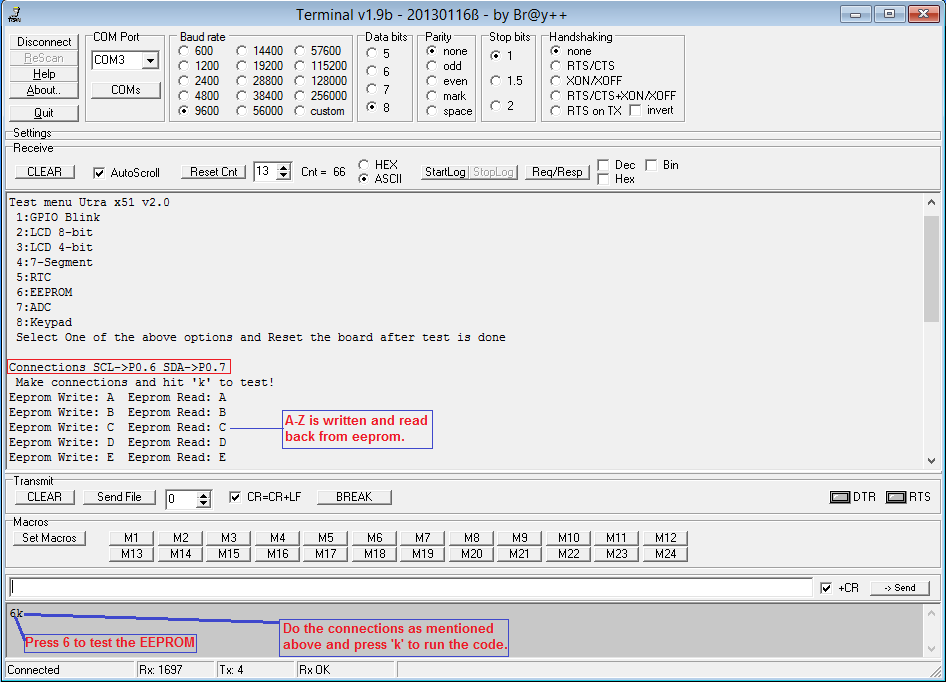
EEprom Test
(A-Z) is written to EEPROM and then read it back. Same is transmitted on UART.
The AT24cxx Eeprom pins are connected to P0 (SCL-P0.6,SDA-P0.7).

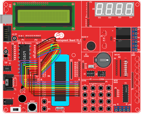
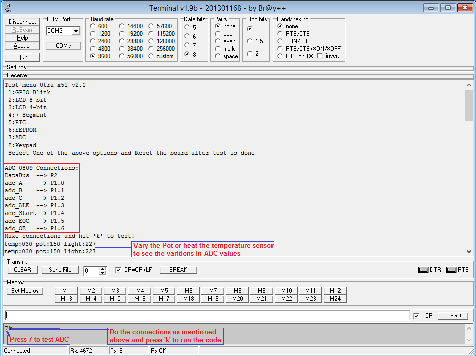
Adc Test
Ultra Board has a Pot, LDR and a temperature sensor. ADC values from these sensors is read and transmitted on UART. Below table shows the sensor pin connection.
| ADC DataBus(D0:D7) | A | B | C | ALE | START | EOC | OE |
|---|---|---|---|---|---|---|---|
| P2(P2_0:P2_7) | P1_0 | P1_1 | P1_2 | P1_3 | P1_4 | P1_5 | P1_6 |
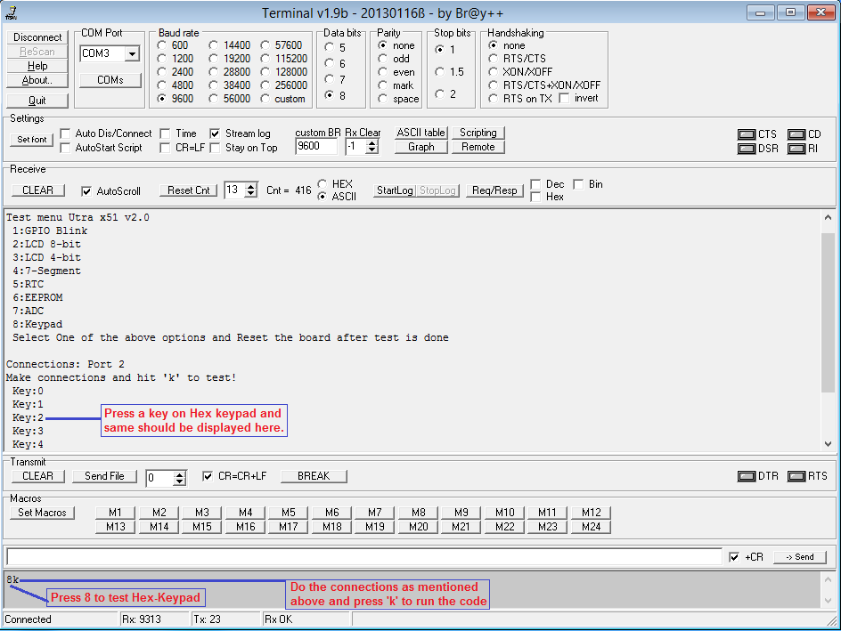
Keypad Test
Below table shows the hex keypad Row-Col pin connection.
| R1 | R2 | R3 | R4 | C1 | C2 | C3 | C4 |
|---|---|---|---|---|---|---|---|
| P2_0 | P2_1 | P2_2 | P2_3 | P2_4 | P2_5 | P2_6 | P2_7 |
Downloads
Have an opinion, suggestion , question or feedback about the article let it out here!

