Difference between revisions of "8051 Led Blinking"
| Line 38: | Line 38: | ||
===Example 2=== | ===Example 2=== | ||
| − | + | In this example, we will see how to access a single port pin to blink the LED. | |
| − | + | ||
<html> | <html> | ||
| − | <script src="https://gist.github.com/SaheblalBagwan/ | + | <script src="https://gist.github.com/SaheblalBagwan/eb446d21ebdc716914458c6c7fc41a60.js"></script> |
</html> | </html> | ||
<br><br> | <br><br> | ||
Revision as of 19:37, 3 September 2016
Light Emitting Diodes (LEDs) are simple and most commonly used electronic components to display the digital signal states. The LED emits light when current is passed through it. It could blow up if we pass more current, hence we put a current limiting resistor. Usually, 220, 470 and 1K ohm resistors are commonly used as limiting resistors. You can use any of these depending on the required brightness.
Lets, start blinking with LEDs and then generate the different patterns using the available LEDs.
Contents
8051 Ports
The basic and important feature of any controllers is the number of GPIO's available for connecting the peripherals. 8051 has 32-gpio's grouped into 4-Ports namely P0-P3 as shown in the below table.
| PORT | Number of Pins | Alternative Function |
| P0 | 8 (P0.0-P0.7) | AD0-AD7 (Address and Data bus) |
| P1 | 8 (P1.0-P1.7) | None |
| P2 | 8 (P2.0-P2.7) | A8-A15 (Higher Address Bus) |
| P3 | 8 (P3.0-P3.7) | UART, Interrupts, (T0/T1)Counters |
As shown in the above table many I/O pins have multiple functions. If a pin is used for other function then it may not be used as a gpio.
Hardware Connections
Examples
Example 1
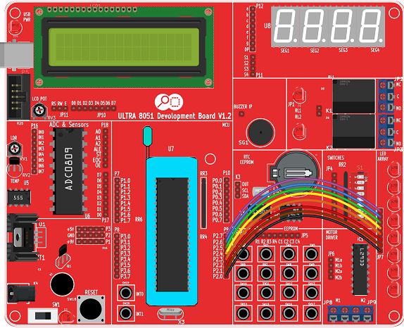
Program to demonstrate the LED blinking. LED's are connected to P2 as shown in the above image.
LEDs are turned ON by sending a high pulse (All Ones).
After some time the LEDs are turned OFF by sending the low pulse (All Zeros).
Example 2
In this example, we will see how to access a single port pin to blink the LED.
Using Explore Embedded Libraries :
In the above tutorial we just discussed how to configure the PORTS for GPIO for blinking the Leds.
Once you know the GPIO configurations, you can directly use the ExploreEmbedded libraries to play around with LEDs.
For that you need to include the gpio.c/gpio.h and the associated files(delay/stdutils).
The below sample code shows how to use the GPIO functions.
Refer this link for more info on GPIO libraries.
Downloads
Download the complete project folder from the below link:
https://codeload.github.com/ExploreEmbedded/Explore-Cortex-M3-LPC1768-Stick-DVB-14001/zip/master
{{#widget:Facebook_Like_Box|profile=https://www.facebook.com/ExploreEmbedded}}
Have a opinion, suggestion , question or feedback about the article let it out here!

