Difference between revisions of "Setting Up Starter AVR"
Raghavendra (Talk | contribs) |
|||
| (2 intermediate revisions by the same user not shown) | |||
| Line 17: | Line 17: | ||
| − | [[File:starter2.JPG]] | + | [[File:starter2.JPG|x400px]] |
=Software Setup= | =Software Setup= | ||
Latest revision as of 18:58, 25 August 2016
In this tutorial we will look at setting up the starter AVR board. Once you have done with this basic set up, you can use on board peripherals as well as many other peripherals which can be connected to board using on board GPIO's.
Basics
This board comes with a ATmega 32 microcontroller, which has arduino bootloader flashed into it.
To program this board using SPI and external programmer check out our AVR Hardware and Software Setup tutorial
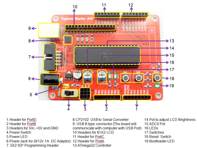
As starter AVR board comes with inbuilt arduino boot loader and this board has on board USB to serial converter indicated by '8' in below diagram so you need to connect only B type USB cable to port indicated by '9' in below diagram.

Hookup
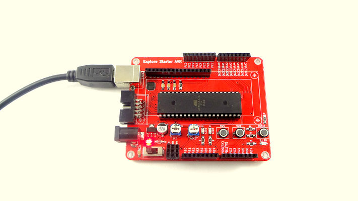
To power up and program the starter AVR board connect type B USB cable as shown in figure. For installing drivers for starter AVR board check out our Installing CP2102 USB Drivers tutorial.
Software Setup
In this tutorial series we are using "Xplore Flash" software to program the target MCU. Download Xplore Flash GUI.
Steps below show how to trasfer the hex file to the MCU using Xplore Flash.
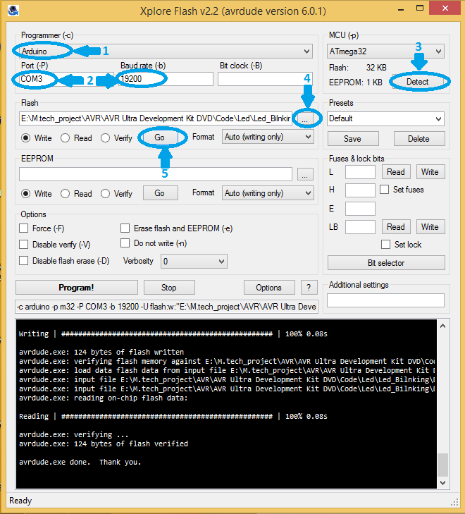
- Open the Xplore Flash and select programmer as Arduino .
- Connect the starter AVR board to computer, it will detect as a COM port. Select detected COM port and set baud rate 19200 .
- Click on Detect, it will detect the MCU as ATmega32.
- After detecting the MCU browse the hex file .
- Then just click on Go, It will erase, Flash and verifies the hex file.
Checkout the Blinky with Starter AVR tutorial, on how to set up the software, generate a hex file and blink an LED.


