
PIC C Library
Contents
Introduction
Overview:
This manual is designed to help embedded programmers and students, rapidly exploit the Pic(16f877A)-Controller for embedded applications. This manual has been targeted at embedded systems programmers and Students who have basic knowledge of Pic(16f877A/PIC18f) architecture and C-Language.
This manual provides the reference to all the library functions which are grouped under respective .c file. The .c files convention is as per the peripherals. The peripherals (lcd, keypad..) are connected to default PORTs which can be connect to required PORTs by changing the #define..
Reference:
It is recommended to go through the below reference documents and datasheets before interfacing any peripherals.
- The Pic Microcontroller and Embedded Systems by Muhammad Ali Mazidi.
- Pic16f877A DataSheet.
- Embedded C by Michael J Pont .
- Any of the 16x2 lcd datasheet.
- RTC-DS1307 from Dallas Semiconductors.
Feedback:
Suggestions for additions and improvements in code and documentation are always welcome. Please send your feedback via e-mail to feedback@xplorelabz.com
Disclaimer:
The libraries have been tested for Pic16f877A on different development boards. We strongly believe that the library works on any Pic16f877A boards. However, Xplore Labz disclaims any kind of hardware failure resulting out of usage of libraries, directly or indirectly. Documentation may be subject to change without prior notice.
The usage of tools and software demonstrated in the document are for educational purpose only, all rights pertaining to these belong to the respective owners. Users must ensure license terms are adhered to, for any use of the demonstrated software.
GNU GENERAL PUBLIC LICENSE: The library code in this document is licensed under GNU General Public License (GPL) Copyright (C) 2012. Everyone is permitted to copy and distribute verbatim copies of this license document, but changing it is not allowed. Since the library is licensed free of charge, there is no warranty for the libraries and the entire risk of the quality and performance is with the user.
Errors and omissions should be reported to: feedback@xplorelabz.com
ADC
Pic ADC library.
- Filename: adc.c
- Controller: Pic16f877A
- Oscillator: 20 MHz
- Author: XploreLabz
- website: www.xplorelabz.com
- Reference:Pic16f877a dataSheet
#include<htc.h>
#include "delay.h"
#include "adc.h"
ADC_Init()
- Description :This function initializes the ADC control registers.
- I/P Arguments: none
- Return value : none
void ADC_Init()
 {
   ADCON0=0x00;    // sampling freq=osc_freq/2,ADC off initially
   ADCON1=0x80;    // All pins are configured as adc and the result is right justified
  }
ADC_StartConversion()
- Description :This function does the ADC conversioin for the Selected Channel and returns the converted 10bit result.
- I/P Arguments: char(channel number).
- Return value : int(10 bit ADC result)
unsigned int ADC_StartConversion(unsigned char channel)
 {
    ADCON0=((1<<ADON) | (channel<<3));   //select particular channel and turn ON adc
    delay_us(50);

    GO=1;                      // Start ADC conversion
    while(GO==1);            // Wait for the conversion to complete

    return((ADRESH<<8) + ADRESL); // return right justified 10-bit result
   }
Delay
PIC delay library with the crystal frequency 20Mhz
- Filename: delay.c
- Controller: Pic16F877A
- Oscillator: 20MHz
- Author: XploreLabz
- website: www.xplorelabz.com
#include<htc.h>
#define DelayCountFor1msec 300
delay_us()
- Description : This function is used generate delay in us.
- It genarates a approximate delay of 3us for each count
- if 50 is passed as the argument then it generates a delay of apprx 150us.
- I/P Arguments: unsigned int
- Return value : none
void delay_us(unsigned int us_count)
 {
    while(us_count!=0)
      {
		 us_count--;
	   }
   }
delay_ms()
- Description: This function is used generate delay in ms.
- It genarates a approximate delay of 1ms for each count
- if 1000 is passed as the argument then it generates delay of apprx 1000ms(1sec)
- I/P Arguments: unsigned int
- Return value : none
void delay_ms(unsigned int ms_count)
 {
       while(ms_count!=0)
	    {
	      delay_us(DelayCountFor1msec);	//delay_us is called to generate 1ms delay
	         ms_count--;
	     }

   }
delay_sec()
- Description: This function is used generate delay in sec .
- It genarates a approximate delay of 1sec for each count,
- if 10 is passed as the argument then it generates delay of apprx 10sec
- I/P Arguments: unsigned char
- Return value : none
Note:
- A max of 255 sec delay can be generated wsing this function.
void delay_sec(unsigned char sec_count)
 {


	 while(sec_count!=0)
	  {
	     delay_ms(1000);	//delay_ms is called to generate 1sec delay
		 sec_count--;
		}
  }
Lcd_8_bit Mode
PIC LCD library for 8-bit mode
- Filename: lcd_8_bit.c
- Controller: Pic16F877A
- Oscillator: 20MHz
- Author: XploreLabz
- website: www.xplorelabz.com
Note:
- Pin connection for LCD display in 8-bit mode is as shown below.
- By default the LCD is connected to PORTB.
- The code can be modified to connect the LCD to any of the PORTs by changing the "#define databus PORTB".

#include<htc.h>
#include "delay.h"
#include "lcd.h"

#define databus	PORTB             //	LCD databus connected to PORTB

#define DataBusDirection TRISB    //Data and Control bus direction config registers
#define ControlBusDirection TRISD

#define rs RD0		 // Register select pin connected to PORTD.0
#define rw RD1		 // Read Write pin connected to PORTD.1
#define en RD2		 // Enable pin connected to PORTD.2


/* 16x2 LCD Specification */
#define LCDMaxLines 2
#define LCDMaxChars 16
#define LineOne 0x80
#define LineTwo 0xc0

#define BlankSpace ' '
LCD_Init()
- Function name: LCD_Init()
- Description :This function is used to initialize the lcd in 8-bit mode.
- I/P Arguments: none
- Return value : none
void LCD_Init()
{
    delay_us(5000);

   DataBusDirection=0x00; //Configure data and control bus as output
   ControlBusDirection=0x00;

   LCD_CmdWrite(0x38);  // LCD 2lines, 5*7 matrix
   LCD_CmdWrite(0x0E);	 // Display ON cursor ON
   LCD_CmdWrite(0x01);	 // Clear the LCD
   LCD_CmdWrite(0x80);	 // Move the Cursor to First line First Position

}
LCD_Clear()
- Description :This function clears the LCD and moves the cursor to first Position.
- I/P Arguments: none
- Return value : none
void LCD_Clear()
{
   LCD_CmdWrite(0x01);	// Clear the LCD and go to First line First Position
   LCD_CmdWrite(LineOne);
}
LCD_GoToLineOne()
- Description :This function moves the Cursor to First line First Position.
- I/P Arguments: none
- Return value : none
void LCD_GoToLineOne()
{
   LCD_CmdWrite(LineOne);	// Move the Cursor to First line First Position
}
LCD_GoToLineTwo()
- Description :This function moves the Cursor to Second line First Position.
- I/P Arguments: none
- Return value : none
void LCD_GoToLineTwo()
{
   LCD_CmdWrite(LineTwo);	// Move the Cursor to Second line First Position
}
LCD_GoToXY()
- Description :This function moves the Cursor to specified position.
- I/P Arguments: char row,char col
- row -> line number(line1=0, line2=1),
- For 2line LCD the I/P argument should be either 0 or 1.
- col -> char number.
- For 16-char LCD the I/P argument should be betwen 0-15.
- Return value : none
void LCD_GoToXY(char row, char col)
{
   char pos;

    if(row<LCDMaxLines)
      {
		 pos= LineOne | (row << 6); // take the line number
		                            //row0->pos=0x80  row1->pos=0xc0

	    if(col<LCDMaxChars)
		   pos= pos+col;            //take the char number
		                            //now pos points to the given XY pos

		 LCD_CmdWrite(pos);	       // Move the Cursor to specified Position
       }
}
LCD_CmdWrite()
- Description :This function sends a command to LCD in the following steps.
- step1: Send the I/P command to LCD.
- step2: Select the Control Register by making RS low.
- step3: Select Write operation making RW low.
- step4: Send a High-to-Low pulse on Enable PIN with some delay_us.
- I/P Arguments: 8-bit command supported by LCD.
- Return value : none
void LCD_CmdWrite( char cmd)
{

   databus=cmd;        // Send the command to LCD
     rs=0;             // Select the Command Register by pulling RS LOW
     rw=0;             // Select the Write Operation  by pulling RW LOW
     en=1;             // Send a High-to-Low Pusle at Enable Pin
 delay_us(10);
     en=0;

   delay_ms(1);
}
LCD_DataWrite()
- Description :This function sends a character to be displayed on LCD in the following steps.
- step1: Send the character to LCD.
- step2: Select the Data Register by making RS high.
- step3: Select Write operation making RW low.
- step4: Send a High-to-Low pulse on Enable PIN with some delay_us.
- I/P Arguments: ASCII value of the char to be displayed.
- Return value : none
void LCD_DataWrite( char dat)
{


   databus=dat;	    // Send the data to LCD
     rs=1;			// Select the Data Register by pulling RS HIGH
     rw=0;			// Select the Write Operation  by pulling RW LOW
     en=1;			// Send a High-to-Low Pusle at Enable Pin
 delay_us(10);
     en=0;

   delay_ms(1);

}
LCD_DisplayString()
- Description :This function is used to display the ASCII string on the lcd.
- The string_ptr points to the first char of the string and traverses till the end(NULL CHAR).
- Each time a char is sent to LCD_DataWrite funtion to display.
- I/P Arguments: String(Address of the string) to be displayed.
- Return value : none
void LCD_DisplayString(char *string_ptr)
{
   while(*string_ptr)
    LCD_DataWrite(*string_ptr++);
  }
LCD_DisplayNumber()
- Function name: LCD_DisplayNumber()
- I/P Arguments: unsigned int
- Return value : none
- Description :This function is used to display a 5-digit integer(0-65535).
- ex:
- if the number is 12345 then 12345 is displayed.
- if the number is 123 then 00123 is displayed.

void LCD_DisplayNumber(unsigned int num)
{
   LCD_DataWrite((num/10000)+0x30);
   num=num%10000;

   LCD_DataWrite((num/1000)+0x30);
   num=num%1000;

   LCD_DataWrite((num/100)+0x30);
   num=num%100;

   LCD_DataWrite((num/10)+0x30);

   LCD_DataWrite((num%10)+0x30);

 }
LCD_ScrollMessage()
- Description :This function scrolls the given message on the first line.
- 16 chars are displayed at atime.
- Pointer is incremented to skip a char each time to give the illusion of moving chars.
- If the chars are less than 16, then the BlankSpaces are displayed.
- I/P Arguments: char *msg_ptr (msg_ptr -> pointer to the string to be scrolled)
- Return value : none
void LCD_ScrollMessage(char *msg_ptr)
{
  unsigned char i,j;
  LCD_CmdWrite(0x0c);			 //Disable the Cursor
  for(i=0;msg_ptr[i];i++)        //Loop to display the complete string
    {                            //each time 16 chars are displayed and
                                 //pointer is incremented to point to next char

      LCD_GoToLineOne();                   //Move the Cursor to first line

      for(j=0;j<LCDMaxChars && msg_ptr[i+j];j++) //loop to Display first 16 Chars
	    LCD_DataWrite(msg_ptr[i+j]);                 //or till Null char

	  for(j=j; j<LCDMaxChars; j++)               //If the chars are below 16
        LCD_DataWrite(BlankSpace);              //then display blank spaces

       delay_ms(300);
    }
   LCD_CmdWrite(0x0E);			  //Enable the Cursor
}
LCD_DisplayRtcTime()
- I/P Arguments: char hour,char min,char sec (hour,min,sec should be packed BCD format, as read from DS1307)
- Return value : none
- Description :This function display hour,min,sec read from DS1307.

void LCD_DisplayRtcTime(char hour,char min,char sec)
{
    LCD_DataWrite(((hour>>4) & 0x0f) + 0x30);
    LCD_DataWrite((hour & 0x0f) + 0x30);
    LCD_DataWrite(':');

    LCD_DataWrite(((min>>4) & 0x0f) + 0x30);
    LCD_DataWrite((min & 0x0f) + 0x30);
    LCD_DataWrite(':');

    LCD_DataWrite(((sec>>4) & 0x0f) + 0x30);
    LCD_DataWrite((sec & 0x0f) + 0x30);

 }
LCD_DisplayRtcDate()
- I/P Arguments: char day,char month,char year (day,month,year should be packed BCD format, as read from DS1307)
- Return value : none
- Description :This function display day,month,year read from DS1307.
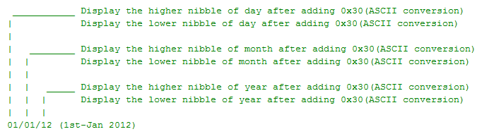

void LCD_DisplayRtcDate(char day,char month,char year)
 {
     LCD_DataWrite(((day>>4) & 0x0f) + 0x30);
     LCD_DataWrite((day & 0x0f) + 0x30);
     LCD_DataWrite('/');

     LCD_DataWrite(((month>>4) & 0x0f) + 0x30);
 	 LCD_DataWrite((month & 0x0f) + 0x30);
     LCD_DataWrite('/');

     LCD_DataWrite(((year>>4) & 0x0f) + 0x30);
 	LCD_DataWrite((year & 0x0f) + 0x30);

 }
Lcd_4_bit Mode
Pic LCD library for 4-bit mode
- Filename: lcd_4_bit.c
- Controller: Pic16F877A
- Oscillator: 20 MHz
- Author: XploreLabz
- website: www.xplorelabz.com
Note:
- Pin connection for LCD display in 4-bit mode.
- By default the LCD is connected to PORTB.
- The code can be modified to connect the LCD to any of the PORTs by changing the "#define databus PORTB".

#include<htc.h>
#include "delay.h"
#include "lcd.h"

#define databus	PORTB             //LCD databus connected to PORTB
#define DataBusDirection TRISB    //Data and Control bus direction config registers

#define rs RB0		          // Register select pin connected to PORTB.0
#define rw RB1		          // Read Write pin connected to PORTB.1
#define en RB2		         // Enable pin connected to PORTB.2
/* 16x2 LCD Specification */
#define LCDMaxLines 2
#define LCDMaxChars 16
#define LineOne 0x80
#define LineTwo 0xc0
#define BlankSpace ' '
LCD_Init()
- Description :This function is used to initialize the lcd in 4-bit mode.
- Function name: LCD_Init()
- I/P Arguments: none
- Return value : none
void LCD_Init()
{
    delay_us(5000);
   DataBusDirection=0x00; //Configure data and control bus as output
   LCD_CmdWrite(0x02);	//Initilize the LCD in 4bit Mode
   LCD_CmdWrite(0x28);
   LCD_CmdWrite(0x0E);	// Display ON cursor ON
   LCD_CmdWrite(0x01);	// Clear the LCD
   LCD_CmdWrite(0x80);	// Move the Cursor to First line First Position

}
LCD_CmdWrite()
- Description :This function sends a command to LCD in the following steps.
- step1: Send the Higher Nibble of the I/P command to LCD.
- step2: Select the Control Register by making RS low.
- step3: Select Write operation making RW low.
- step4: Send a High-to-Low pulse on Enable PIN with some delay_us.
- step5: Send the Lower Nibble of the I/P command to LCD.
- step6: Select the Control Register by making RS low.
- step7: Select Write operation making RW low.
- step8: Send a High-to-Low pulse on Enable PIN with some delay_us.
- I/P Arguments: 8-bit command supported by LCD
- Return value : none
void LCD_CmdWrite( char cmd)
{
   databus=(cmd & 0xf0);        // Send the Higher Nibble of the command to LCD
     rs=0;				    // Select the Command Register by pulling RS LOW
     rw=0;				    // Select the Write Operation  by pulling RW LOW
     en=1;				    // Send a High-to-Low Pusle at Enable Pin
  delay_us(10);
     en=0;

   delay_us(10);					// wait for some time

   databus=((cmd<<4) & 0xf0);  // Send the Lower Nibble of the command to LCD
     rs=0;				    // Select the Command Register by pulling RS LOW
     rw=0;				    // Select the Write Operation  by pulling RW LOW
     en=1;			          // Send a High-to-Low Pusle at Enable Pin
  delay_us(10);
     en=0;

   delay_ms(1);
}
LCD_DataWrite()
- Function name: LCD_DataWrite()
- Description :This function sends a character to be displayed on LCD in the following steps.
- step1: Send the higher nibble of the character to LCD.
- step2: Select the Data Register by making RS high.
- step3: Select Write operation making RW low.
- step4: Send a High-to-Low pulse on Enable PIN with some delay_us.
- step5: wait for some time
- step6: Send the lower nibble of the character to LCD.
- step7: Select the Data Register by making RS high.
- step8: Select Write operation making RW low.
- step9: Send a High-to-Low pulse on Enable PIN with some delay_us.
- I/P Arguments: ASCII value of the char to be displayed.
- Return value : none
void LCD_DataWrite( char dat)
{


   databus=(dat & 0xf0);	    // Send the Higher Nibble of the Data to LCD
     rs=1;			   // Select the Data Register by pulling RS HIGH
     rw=0;			  // Select the Write Operation  by pulling RW LOW
     en=1;			 // Send a High-to-Low Pusle at Enable Pin
  delay_us(10);
     en=0;

   delay_us(10);		 // wait for some time.

   databus=((dat <<4) & 0xf0);	// Send the Lower Nibble of the Data to LCD
     rs=1;			// Select the Data Register by pulling RS HIGH
     rw=0;			// Select the Write Operation  by pulling RW LOW
     en=1;			// Send a High-to-Low Pusle at Enable Pin
 delay_us(10);
     en=0;

   delay_ms(1);

}
Keypad
PIC 4x4 Keypad Library
- Filename: keypad.c
- Controller: Pica6f877A
- Oscillator: 20 MHz
- Author: XploreLabz
- website: www.xplorelabz.com
Note:
- Rows are connected to lower 4-bits of PORTC.
- Cols are connected to higher 4-bits of PORTC.

#include <htc.h>
#include "keypad.h"
#include "delay.h"

#define RowColDirection TRISC //Data Direction Configuration for keypad

#define ROW PORTC   //Lower four bits of P1 are used as ROWs
#define COL PORTC  //Higher four bits of P1 are used as COLs
KEYPAD_Init()
- Description : This function the rows and colums for keypad scan
- ROW lines are configured as Output.
- Column Lines are configured as Input.
- I/P Arguments:none
- Return value : none
void KEYPAD_Init()
{
       RowColDirection=0x0f;    // Configure Row lines as O/P and Column lines as I/P
}
KEYPAD_WaitForKeyRelease()
- Description : This function waits till the previous key is released.
- All the ROW lines are pulled high.
- Column Lines are read to check the key press.
- If all the Keys are released then Column lines will be low(0x00) .
- I/P Arguments:none
- Return value : none
void KEYPAD_WaitForKeyRelease()
{
   unsigned char key;
    do
	  {
        ROW=0xF0;           // Pull the ROW lines to high and Column lines low.
	    key=COL & 0x0f;   // Read the Columns, to check the key press
       }while(key!=0x00);  // Wait till the Key is released,
                              // If no Key is pressed, Column lines will be low(0x00)
}
KEYPAD_WaitForKeyPress()
- Description : This function waits till a new key is pressed.
- All the ROW lines are pulled high.
- Column Lines are read to check the key press.
- If any Key is pressed then corresponding Column Line goes high.
- Wait for Some time and perform the above operation to ensure the True Key Press before decoding the KEY.
- I/P Arguments:none
- Return value : none
void KEYPAD_WaitForKeyPress()
{
  unsigned char key;
  do
   {
	 do
      {
	    ROW=0xF0;		 // Pull the ROW lines to high and Column lines low.
	    key=COL & 0x0F;	 // Read the Columns, to check the key press
	  }while(key==0x00);  // Wait till the Key is pressed,
					 // if a Key is pressed the corresponding Column line go high

	   delay_ms(1);		  // Wait for some time(debounce Time);

	   ROW=0xF0;		  // After debounce time, perform the above operation
	   key=COL & 0x0F;	  // to ensure the Key press.

	}while(key==0x00);

 }
KEYPAD_ScanKey()
- Description : This function scans all the rows to decode the key pressed.
- Each time a ROW line is pulled high to detect the KEY.
- Column Lines are read to check the key press.
- If any Key is pressed then corresponding Column Line goes high.
- Return the ScanCode(Combination of ROW & COL) for decoding the key.
- I/P Arguments:none
- Return value : char--> Scancode of the Key Pressed
unsigned char KEYPAD_ScanKey()
 {

	 unsigned char ScanKey = 0x10,i, key;

   for(i=0;i<0x04;i++)            // Scan All the 4-Rows for key press
    {
      ROW=ScanKey;                // Select 1-Row at a time for Scanning the Key
      key=COL & 0x0F;             // Read the Column, for key press

      if(key!=0x00)               // If the KEY press is detected for the selected
         break;                   // ROW then stop Scanning,

     ScanKey=(ScanKey<<1); // Rotate the ScanKey to SCAN the remaining Rows
    }


    key = key | ScanKey;         // Retun the row and COL status to decode the key
    return(key);
}
KEYPAD_GetKey()
- Description: This function waits till a key is pressed and retuns its ASCII Value
- Wait till the previous key is released..
- Wait for the new key press.
- Scan all the rows one at atime for the pressed key.
- Decode the key pressed depending on ROW-COL combination and retuns its ASCII value.
- I/P Arguments:none
- Return value : char--> ASCII value of the Key Pressed
unsigned char KEYPAD_GetKey()
{
	unsigned char key;

      KEYPAD_WaitForKeyRelease();    // Wait for the previous key release
      delay_ms(1);

      KEYPAD_WaitForKeyPress();      // Wait for the new key press
      key = KEYPAD_ScanKey();        // Scan for the key pressed.

   switch(key)                       // Decode the key
     {
         case 0x11: key='7'; break;
         case 0x12: key='8'; break;
         case 0x14: key='9'; break;
         case 0x18: key='%'; break;
  	   case 0x21: key='4'; break;
	   case 0x22: key='5'; break;
	   case 0x24: key='6'; break;
	   case 0x28: key='*'; break;
	   case 0x41: key='1'; break;
	   case 0x42: key='2'; break;
	   case 0x44: key='3'; break;
	   case 0x48: key='-'; break;
	   case 0x81: key='N'; break;
	   case 0x82: key='0'; break;
	   case 0x84: key='='; break;
	   case 0x88: key='+'; break;
       default: key='z';
      }
   return(key);                      // Return the key
}
UART
PIC UART library for Serial Communication for 9600 baud rate at 20MHz
- Filename: uart.c
- Controller: Pic16F877A
- Oscillator: 20MHz
- Author: XploreLabz
- website: www.xplorelabz.com
#include<htc.h>
UART_Init()
- Description :This function is used to initialize the UART at 9600 baud rate by below configuration.
- TXSTA is configured for Asynchronous mode, 8-bit data & transmitter enabled.
- RCSTA is configured for continous receive enable.
- SPBRG is configured 9600 Baud rate at 20MHz.
- I/P Arguments: none
- Return value : none
void UART_Init()
{
    TRISC=0x80;      // Configure Rx pin as input and Tx as output
  	TXSTA=0x20;      // Asynchronous mode, 8-bit data & enable transmitter
	RCSTA=0x90;      // 8-bit continous receive enable
	SPBRG=31;        // 9600 Baud rate at 20MHz
  }
UART_RxChar()
- Description :This function is used to receive a char from UART module.
- It waits till a char is received ie.till RCIF is set,
- RCIF will be set once a CHAR is received.
- Finally it clears the RCIF for next cycle and returns the received char.
- I/P Arguments: none
- Return value : char
char UART_RxChar()
{
   while(RCIF==0);    // Wait till the data is received
     RCIF=0;            // Clear receiver flag
   return(RCREG);        // Return the received data to calling function
}
UART_TxChar()
- Description :This function is used to transmit a char through UART module.
- It waits till previous char is transmitted ie.till TXIF is set.
- TXIF will be set once a CHAR is transmitted.
- It clears the TXIF for next operation.
- Finally the Char to be transmitted is loaded into TXREG.
- I/P Arguments: char--> data to be transmitted.
- Return value : none
 void UART_TxChar(char ch)
{
   while(TXIF==0);  // Wait till the transmitter register becomes empty
	TXIF=0;        // Clear transmitter flag
      TXREG=ch;        // load the chr the to be transmitted into transmit reg
}
UART_TxString()
- Description :This function is used to transmit the ASCII string through UART.
- The string_ptr points to the first char of the string.
- And it is incremented each time to traverse till the end(NULL CHAR).
- Each time a char is sent to UART_TxChar() fun to transmit it through UART
- I/P Arguments: String(Address of the string) to be transmitted.
- Return value : none
void UART_TxString(char *string_ptr)
 {
          while(*string_ptr)
           UART_TxChar(*string_ptr++);
   }
UART_RxString()
- Description :
- This function is used to receive a ASCII string through UART till the carriage_return/New_line.
- The string_ptr points to the begining of the string and each time UART_RxChar() function is called to receive a char and copy it into the buffer(STRING) and incrment string_ptr.
- Once the carriage_return/New_line is encountered the loop is breaked and the String is NULL terminated.
- I/P Arguments: *string_ptr (Address of the string where the received data needs to be stored)
- Return value : none
NOTE:
- The received char is ECHOED back, if not required then comment UART_TxChar(ch) in the code.
- BackSlash is not taken care.
void UART_RxString(char *string_ptr)
 {
     char ch;
     while(1)
       {
          ch=UART_RxChar();    //Receive a char
          UART_TxChar(ch);     //Echo back the received char

        if((ch=='\r') || (ch=='\n')) //read till enter key is pressed
           {				     //once enter key is pressed
              *string_ptr=0;            //null terminate the string
                break;			     //and break the loop
             }
         *string_ptr=ch;                //copy the char into string.
         string_ptr++;			    //and increment the pointer
      }
 }
UART_TxNumber()
- I/P Arguments: unsigned int.
- Return value : none
- Description :This function is used to transmit a 5-digit integer(0-65535).
- ex:
- if the number is 12345 then 12345 is transmitted.
- if the number is 123 then 00123 is transmitted.

void UART_TxNumber(unsigned int num)
{

	   UART_TxChar((num/10000)+0x30);
	   num=num%10000;

	   UART_TxChar((num/1000)+0x30);
	   num=num%1000;

	   UART_TxChar((num/100)+0x30);
	   num=num%100;

	   UART_TxChar((num/10)+0x30);

       UART_TxChar((num%10)+0x30);
}
I2C
PIC I2C library
- Filename: I2C.c
- Controller: Pic16f877A(PIC family)
- Oscillator: 11.0592 MHz
- Author: XploreLabz
- website: www.xplorelabz.com
Note:
- The SDA and SCL lines are connected to PORTC.4 and PORTC.3
- The code can be modified to connect the SDA and SCL to any of the PORTs by changing the #define
#include<reg51.h>
#include "delay.h"
#include "i2c.h"

sbit SCL=RC3;      //SCL Connected to PORTC.3
sbit SDA=RC4;      //SDA Connected to PORTC.4
I2C_Clock()
- Description :This function is used to generate a clock pulse on SCL line.
- I/P Arguments: none
- Return value : none
void I2C_Clock(void)
{
    delay_us(1);
    SCL = 1;        // Wait for Some time and Pull the SCL line High

    delay_us(1);        // Wait for Some time
    SCL = 0;        // Pull back the SCL line low to Generate a clock pulse
}
I2C_Start()
- I/P Arguments: none
- Return value : none
- Description :This function is used to generate I2C Start Condition.
- Start Condition: SDA goes low when SCL is High.

void I2C_Start()
{
    SCL = 0;        // Pull SCL low

    SDA = 1;        // Pull SDA High
    delay_us(1);

    SCL = 1;        //Pull SCL high
    delay_us(1);

    SDA = 0;        //Now Pull SDA LOW, to generate the Start Condition
    delay_us(1);

    SCL = 0;        //Finally Clear the SCL to complete the cycle
}
I2C_Stop()
- I/P Arguments: none
- Return value : none
- Description :This function is used to generate I2C Stop Condition.
- Stop Condition: SDA goes High when SCL is High.

void I2C_Stop(void)
{
    SCL = 0;            // Pull SCL low
    delay_us(1);

    SDA = 0;            // Pull SDA  low
    delay_us(1);

    SCL = 1;            // Pull SCL High
    delay_us(1);

    SDA = 1;            // Now Pull SDA High, to generate the Stop Condition
}
I2C_Write()
- I/P Arguments: unsigned char-->8bit data to be sent.
- Return value : none
- Description :This function is used to send a byte on SDA line using I2C protocol
- 8bit data is sent bit-by-bit on each clock cycle.
- MSB(bit) is sent first and LSB(bit) is sent at last.
- Data is sent when SCL is low.

void I2C_Write(unsigned char dat)
{
    unsigned char i;

    for(i=0;i<8;i++)         // loop 8 times to send 1-byte of data
     {
        SDA = dat & 0x80;    // Send Bit by Bit on SDA line
        I2C_Clock();         // Generate Clock at SCL
        dat = dat<<1;
      }
        SDA = 1;                 // Set SDA at last
}
I2C_Read()
- I/P Arguments: none
- Return value : Unsigned char(received byte)
- Description :This fun is used to receive a byte on SDA line using I2C protocol.
- 8bit data is received bit-by-bit each clock and finally packed into Byte.
- MSB(bit) is received first and LSB(bit) is received at last.

unsigned char I2C_Read(void)
{
    unsigned char i, dat=0x00;

       SDA=1;               //Make SDA as I/P
    for(i=0;i<8;i++)        // loop 8times to read 1-byte of data
     {
       delay_us(1);
        SCL = 1;            // Pull SCL High
        delay_us(1);

        dat = dat<<1;       //dat is Shifted each time and
        dat = dat | SDA;    //ORed with the received bit to pack into byte

        SCL = 0;            // Clear SCL to complete the Clock
       }
   return dat;               // Finally return the received Byte*
}
I2C_Ack()
- Description :This function is used to generate a the Positive ACK pulse on SDA after receiving a byte.
- I/P Arguments: none.
- Return value : none
void I2C_Ack()
{
    SDA = 0;        //Pull SDA low to indicate Positive ACK
    I2C_Clock();    //Generate the Clock
    SDA = 1;        // Pull SDA back to High(IDLE state)
}
I2C_NoAck()
- Description :This function is used to generate a the Negative/NO ACK pulse on SDA after receiving all bytes.
- I/P Arguments: none
- Return value : none
void I2C_NoAck()
{
    SDA = 1;        //Pull SDA high to indicate Negative/NO ACK
   I2C_Clock();     // Generate the Clock
    SCL = 1;        // Set SCL */
}
Ds1307_RTC
PIC DS1307 library
- Filename: DS1307.c
- Controller: Pic16f877A(PIC family)
- Oscillator: 11.0592 MHz
- Author: XploreLabz
- website: www.xplorelabz.com
#include "ds1307.h"
#include "i2c.h"
#include "delay.h"
- Below values are fixed and should not be changed.
- Refer Ds1307 DataSheet for more info.
#define DS1307_ID 0xD0     // DS1307 ID

#define SEC_ADDRESS   0x00 // Address to access Ds1307 SEC register
#define DATE_ADDRESS  0x04 // Address to access Ds1307 DATE register
#define CONTROL 0x07       // Address to access Ds1307 CONTROL register
DS1307_Init()
- Description :This function is used to initialize the Ds1307 RTC.
- Ds1307 ic is enabled by sending the DS1307 id on the I2C bus.
- After selecting DS1307, write 0x00 into Control register of Ds1307
- I/P Arguments: none
- Return value : none
void DS1307_Init()
{
    I2C_Start();            // Start I2C communication

    DS1307_Write(DS1307_ID);   // Connect to DS1307 by sending its ID on I2c Bus
    DS1307_Write(CONTROL);     // Select the Ds1307 ControlRegister to configure Ds1307

    DS1307_Write(0x00);        // Write 0x00 to Control register to disable SQW-Out

    I2C_Stop();             // Stop I2C communication after initilizing DS1307

 }
DS1307_Write()
- Description :This function is used to write a byte of data into Ds1307 RTC.
- This function calls I2C_write function to perform the same.
- I/P Arguments: char-> Data to be written into DS1307.
- Return value : none
void DS1307_Write(unsigned char dat)
{
    I2C_Write(dat);   // Connect to DS1307 by sending its ID on I2c Bus
    I2C_Clock();
 }
DS1307_Read()
- Description : This function is used to read a byte of data from Ds1307 RTC.
- This function calls I2C_Read function to perform the same.
- I/P Arguments: char-> Data to be written into DS1307.
- Return value : none
unsigned char DS1307_Read()
{
    unsigned char dat;
    dat = I2C_Read();   // Connect to DS1307 by sending its ID on I2c Bus
    return(dat);
 }
DS1307_SetTime()
- Description :This function is used to set Time(hh,mm,ss) into the Ds1307 RTC.
- Ds1307 ic is enabled by sending the DS1307 id on the I2C bus.
- After selecting DS1307, select the RAM address 0x00 to point to sec
- Initilze Sec, MIN, Hour one after the other.
- Stop the I2c communication.
- I/P Arguments: char,char,char-->hh,mm,ss to initilize the time into DS1307.
- Return value : none
void DS1307_SetTime(unsigned char hh, unsigned char mm, unsigned char ss)
{
    I2C_Start();            // Start I2C communication

    DS1307_Write(DS1307_ID);    // connect to DS1307 by sending its ID on I2c Bus
    DS1307_Write(SEC_ADDRESS); // Select the SEC RAM address

    DS1307_Write(ss);           // Write sec on RAM address 00H
    DS1307_Write(mm);           // Write min on RAM address 01H
    DS1307_Write(hh);           // Write hour on RAM address 02H

    I2C_Stop();             // Stop I2C communication after Setting the Time
}
DS1307_SetDate()
- Description :This function is used to set Date(dd,mm,yy) into the Ds1307 RTC.
- Ds1307 ic is enabled by sending the DS1307 id on the I2C bus.
- After selecting DS1307, select the RAM address 0x04 to point to day
- Initilze Day,Month and Year one after the other.
- Stop the I2c communication.
- I/P Arguments: char,char,char-->day,month,year to initilize the Date into DS1307.
- Return value : none
void DS1307_SetDate(unsigned char dd, unsigned char mm, unsigned char yy)
{
    I2C_Start();            // Start I2C communication

    DS1307_Write(DS1307_ID);    // connect to DS1307 by sending its ID on I2c Bus
    DS1307_Write(DATE_ADDRESS);     // Request DAY RAM address at 04H

    DS1307_Write(dd);           // Write date on RAM address 04H
    DS1307_Write(mm);           // Write month on RAM address 05H
    DS1307_Write(yy);           // Write year on RAM address 06h

    I2C_Stop();             // Stop I2C communication after Setting the Date
}
DS1307_GetTime()
- Description :This function is used to get the Time(hh,mm,ss) from Ds1307 RTC.
- Ds1307 ic is enabled by sending the DS1307 id on the I2C bus.
- After selecting DS1307, select the RAM address 0x00 to point to sec
- Get Sec, MIN, Hour one after the other.
- Stop the I2c communication.
- I/P Arguments: char *,char *,char *-->pointers to get the hh,mm,ss.
- Return value : none
void DS1307_GetTime(unsigned char *h_ptr,unsigned char *m_ptr,unsigned char *s_ptr)
{
     I2C_Start();           // Start I2C communication

    DS1307_Write(DS1307_ID);    // connect to DS1307 by sending its ID on I2c Bus
    DS1307_Write(SEC_ADDRESS);          // Request Sec RAM address at 00H

     I2C_Stop();            // Stop I2C communication after selecting Sec Register

    I2C_Start();                // Start I2C communication
    DS1307_Write(0xD1);         // connect to DS1307( under Read mode)
                                //by sending its ID on I2c Bus

  *s_ptr = DS1307_Read();  I2C_Ack();     // read second and return Positive ACK
  *m_ptr = DS1307_Read();  I2C_Ack();      // read minute and return Positive ACK
  *h_ptr = DS1307_Read();  I2C_NoAck();   // read hour and return Negative/No ACK

  I2C_Stop();               // Stop I2C communication after reading the Time
 }
DS1307_GetDate()
- Description :This function is used to get the Date(y,m,d) from Ds1307 RTC.
- Ds1307 ic is enabled by sending the DS1307 id on the I2C bus.
- After selecting DS1307, select the RAM address 0x00 to point to DAY
- Get Day, Month, Year one after the other.
- Stop the I2c communication.
- I/P Arguments: char *,char *,char *-->pointers to get the y,m,d.
- Return value : none
void DS1307_GetDate(unsigned char *d_ptr,unsigned char *m_ptr,unsigned char *y_ptr)
{
    I2C_Start();            // Start I2C communication

    DS1307_Write(DS1307_ID);    // connect to DS1307 by sending its ID on I2c Bus
    DS1307_Write(DATE_ADDRESS);     // Request DAY RAM address at 04H

    I2C_Stop();             // Stop I2C communication after selecting DAY Register


   I2C_Start();             // Start I2C communication
   DS1307_Write(0xD1);          // connect to DS1307( under Read mode)
                            // by sending its ID on I2c Bus

  *d_ptr = DS1307_Read(); I2C_Ack();     // read Day and return Positive ACK
  *m_ptr = DS1307_Read(); I2C_Ack();     // read Month and return Positive ACK
  *y_ptr = DS1307_Read(); I2C_NoAck();   // read Year and return Negative/No ACK

  I2C_Stop();         // Stop I2C communication after reading the Time
 }
EEPROM
Pic16f877A EEPROM library
- Filename: eeprom.c
- Controller: Pic16f877A
- Oscillator: 20 MHz
- Author: XploreLabz
- website: www.xplorelabz.com
#include<htc.h>
#include"delay.h"
EEPROM_WriteByte()
- Description:This function is used to write the data at specified EEPROM_address..
- I/P Arguments: char,char-->eeprom_address at which eeprom_data is to be written.
- Return value : none
           .

void EEPROM_WriteByte(unsigned char eeprom_Address, unsigned char eeprom_Data)
{
     while(RD || WR);    // check the WR&RD bit to see if a RD/WR is in progress
   EEADR=eeprom_Address; // Write the address to EEADR.
                         // Make sure that the address is not larger than the memory size
   EEDATA=eeprom_Data;   // load the 8-bit data value to be written in the EEDATA register.
   WREN=1;               // Set the WREN bit to enable eeprom operation.
   EECON2=0x55;          //Execute the special instruction sequence
   EECON2=0xaa;          //Refer the datasheet for more info
   WR=1;                 // Set the WR bit to trigger the eeprom write operation.
   delay_us(10);
   WREN=0;               // Disable eeprom operation.
}
EEPROM_ReadByte()
- Description: This function is used to read the data from specified EEPROM_address.
- I/P Arguments: char-->eeprom_address from where eeprom_data is to be read.
- Return value : char-->data read from Eeprom.
unsigned char EEPROM_ReadByte(unsigned char eeprom_Address)
{
    while(RD || WR);      // check the WR&RD bit to see if a RD/WR is in progress
  EEADR=eeprom_Address;   // Write the address to EEADR.
                          // Make sure that the address is not larger than the memory size
    RD = 1;               // Set the WR bit to trigger the eeprom read operation.
    delay_us(50);
    return(EEDATA);       // Return the data read form eeprom.
 }
EEPROM_WriteNBytes()
- Description: This function is used to write N-bytes of data at specified EEPROM_address.
- EEPROM_WriteByte() function is called to write a byte at atime.
- Source(RAM) and destination(EEPROM) address are incremented after each write
- NoOfBytes is Decemented each time a byte is written.
- Above Operation is carried out till all the bytes are written(NoOfBytes!=0).
- I/P Arguments:
- char,-->eeprom_address from where the N-bytes are to be written.
- char*-->Pointer to the N-bytes of data to be written.
- char --> Number of bytes to be written.
- Return value : none
void EEPROM_WriteNBytes(unsigned char EepromAddr, unsigned char *RamAddr, char NoOfBytes)
 {
  while(NoOfBytes !=  0)
   {
	EEPROM_WriteByte(EepromAddr,*RamAddr); //Write a byte from RAM to EEPROM
	    EepromAddr++;				   //Incerement the Eeprom Address
		RamAddr++;				   //Increment the RAM Address
		NoOfBytes--;			   //Decrement NoOfBytes after writing each Byte
	   }
 }
EEPROM_ReadNBytes()
- Description: This function is used to Read N-bytes of data from specified EEPROM_address.
- EEPROM_ReadByte() func is called to read a byte at a time.
- Source(RAM) and destination(EEPROM) address are incremented each time.
- NoOfBytes is Decemented after a byte is read.
- Above Operation is carried out till all the bytes are read(NoOfBytes!=0).
- I/P Arguments:
- char,-->eeprom_address from where the N-bytes is to be read.
- char*-->Pointer into which the N-bytes of data is to be read.
- char --> Number of bytes to be Read
- Return value : none
void EEPROM_ReadNBytes(unsigned char EepromAddr, unsigned char *RamAddr, char NoOfBytes)
 {
   while(NoOfBytes !=  0)
	{
	 *RamAddr = EEPROM_ReadByte(EepromAddr);//Read a byte from EEPROM to RAM
	    EepromAddr++;				    //Incerement the Eeprom Address
	 	RamAddr++;			          //Increment the RAM Address
	 	NoOfBytes--;			    //Decrement NoOfBytes after Reading each Byte

	 }
 }
EEPROM_WriteString()
- Description:This function is used to Write a String at specified EEPROM_address.
- EEPROM_WriteByte() function is called to write a byte at a time.
- Source(RAM) and destination(EEPOM) address are incremented each time.
- Above Operation is carried out till Null char is identified.
- I/P Arguments:
- char,-->eeprom_address where the String is to be written.
- char*-->Pointer to String which has to be written.
- Return value : none
NOTE:
- Null char is also written into the eeprom.
void EEPROM_WriteString(unsigned char eeprom_address, unsigned char * source_address)
  {
    do
 	{
 	  EEPROM_WriteByte(eeprom_address,*source_address); //Write a byte from RAM to EEPROM
 	    source_address++;				          //Incerement the RAM Address
 		eeprom_address++;					    //Increment the Eeprom Address
 	  }while(*(source_address-1)!=0);
  }
EEPROM_ReadString()
- Description:This function is used to Read a String from specified EEPROM_address.
- EEPROM_ReadByte() function is called to read a byte at a time.
- Source(EEPROM) and destination(RAM) address are incremented each time.
- Above Operation is carried out till Null char is identified.
- I/P Arguments:
- char,-->eeprom_address from where the String is to be read.
- char*-->Pointer into which the String is to be read.
- Return value : none
void EEPROM_ReadString(unsigned char eeprom_address, unsigned char * destination_address)
  {
   char eeprom_data;

     do
 	 {
	  eeprom_data = EEPROM_ReadByte(eeprom_address); //Read a byte from EEPROM to RAM
 	    *destination_address = eeprom_data;	       //Copy the data into String Buffer
 	     destination_address++;				 //Incerement the RAM Address
 	 	 eeprom_address++;				 //Increment the Eeprom Address
 		}while(eeprom_data!=0);
  }
EEPROM_Erase()
- Description:This function is used to erase the entire Eeprom memory.
- Eeprom is filled with 0xFF to accomplish the Eeprom Erase.
- EEPROM_WriteByte() function is called to write a byte at a time.
- Whole memory(0-255) is traversed and filled with 0xFF
- I/P Arguments: none
- Return value : none
  void EEPROM_Erase()
   {
	 unsigned char eeprom_address;

	 for(eeprom_address=0;eeprom_address<255;eeprom_address++)
	    {
		 EEPROM_WriteByte(eeprom_address,0xff); // Write Each memory location with OxFF
	      }
   }