LCD Interface with PIC18F4520 Starter Board
In this tutorial we will see how to interface alpha-numeric LCD with PIC18F4520 starter board.
LCD pin Connection
Starter board comes with on board header to connect 1x16,2x16 or 4x20 LCD in 4-bit Mode.
Below table shows the LCD pins connection.
RS | RW | EN | D0 | D1 | D2 | D3 | D4 | D5 | D6 | D7 |
---|---|---|---|---|---|---|---|---|---|---|
PB_0 | PB_1 | PB_2 | P_NC | P_NC | P_NC | P_NC | PB_4 | PB_5 | PB_6 | PB_7 |
- P_NC: Pin Not Connected
Code
LCD 1x16
This file contains bidirectional Unicode text that may be interpreted or compiled differently than what appears below. To review, open the file in an editor that reveals hidden Unicode characters.
Learn more about bidirectional Unicode characters
#include "lcd.h" | |
int main() | |
{ | |
/*Connect RS->PB0, RW->PB1, EN->PB2 and data bus to PORTB.4 to PORTB.7*/ | |
LCD_SetUp(PB_0,PB_1,PB_2,P_NC,P_NC,P_NC,P_NC,PB_4,PB_5,PB_6,PB_7); | |
LCD_Init(1,16); | |
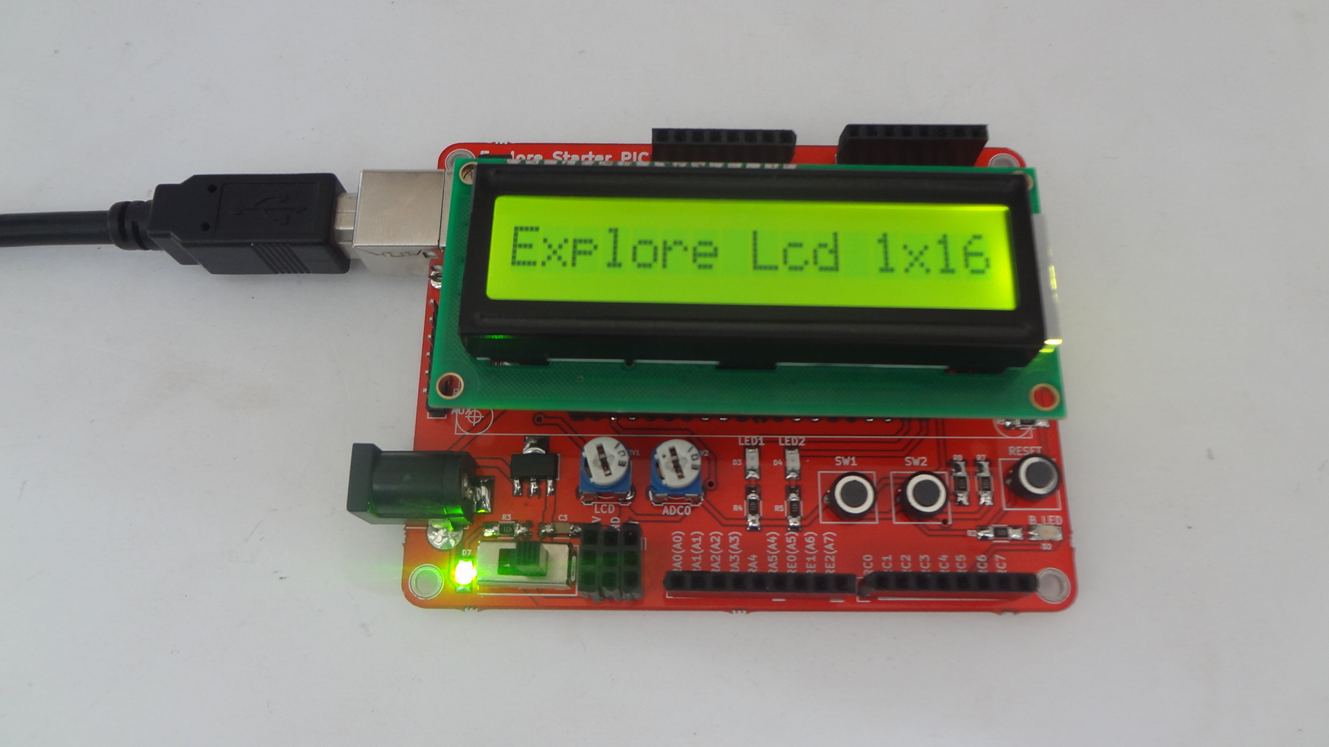
LCD_DisplayString("Explore Lcd 1x16"); | |
while(1); | |
return (0); | |
} |
LCD 2x16
This file contains bidirectional Unicode text that may be interpreted or compiled differently than what appears below. To review, open the file in an editor that reveals hidden Unicode characters.
Learn more about bidirectional Unicode characters
#include "lcd.h" | |
int main() | |
{ | |
/*Connect RS->PB0, RW->PB1, EN->PB2 and data bus to PORTB.4 to PORTB.7*/ | |
LCD_SetUp(PB_0,PB_1,PB_2,P_NC,P_NC,P_NC,P_NC,PB_4,PB_5,PB_6,PB_7); | |
LCD_Init(2,16); | |
LCD_DisplayString("Explore Embedded"); | |
LCD_DisplayString("Lcd 4-bit Mode"); | |
while(1); | |
return (0); | |
} |
LCD 4x20
This file contains bidirectional Unicode text that may be interpreted or compiled differently than what appears below. To review, open the file in an editor that reveals hidden Unicode characters.
Learn more about bidirectional Unicode characters
#include "lcd.h" | |
int main() | |
{ | |
/*Connect RS->PB0, RW->PB1, EN->PB2 and data bus to PORTB.4 to PORTB.7*/ | |
LCD_SetUp(PB_0,PB_1,PB_2,P_NC,P_NC,P_NC,P_NC,PB_4,PB_5,PB_6,PB_7); | |
LCD_Init(4,20); | |
LCD_DisplayString("Explore Embedded\n"); | |
LCD_DisplayString("LCD 4-bit Mode\n"); | |
LCD_DisplayString("20 x 4 \n"); | |
LCD_DisplayString(":) :O"); | |
while(1); | |
return (0); | |
} |
Demo
The images below shows 16x2, 16x1 and 20x4 LCD's interfaced with starter AVR.
Downloads
Download the complete project folder from the below link:
https://github.com/ExploreEmbedded/Pic16f877a_ExploreStarterPIC/archive/master.zip
Have a opinion, suggestion , question or feedback about the article let it out here!