Interrupts On Explore M3
In this tutorial we will discuss how to use the external interrupts on Explore M3.
Prerequisites
Please check this tutorial for detailed explanation on inbuilt Lpc1768 External Interrupts.
If you are doing it for the first time, then check the below links to setup the project for generating the .bin file.
EINTx Pins
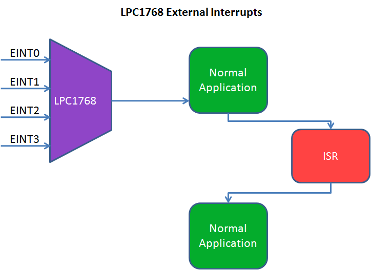
LPC1768 has four external interrupts EINT0-EINT3.
Below table shows mapping of EINTx pins.
| Interrupt | LPC1768 Pin | Explore M3 pin | Enum to be used |
|---|---|---|---|
| EINT0 | P2.10 | ISP | EINT0 |
| EINT1 | P2.11 | USB_BOOT | EINT1 |
| EINT2 | P2_12 | 30 | EINT2 |
| EINT3 | P2.13 | 31 | EINT3 |
Note:
- ISP Pin is used for ISP programming and it should not be zero during RESET, else the controller will in ISP mode.
- USB_BOOT Switch is used for Usb/Dfu bootloader and it should not be zero during RESET, else the controller will in USB/DFU boot mode.
Hardware Connection
LED is Connected to pin 13 on Explore M3 board.
Code
Below is the sample code to blink the LED's with 1ms delay using systick timer.

