Interfacing RTC with Atmega128 Breakout
In this tutorial we will interface the RTC ( Real Time Clock ) with Atmega128 Breakout. We need the following Breakout boards and Display for interfacing.
Contents
Basics
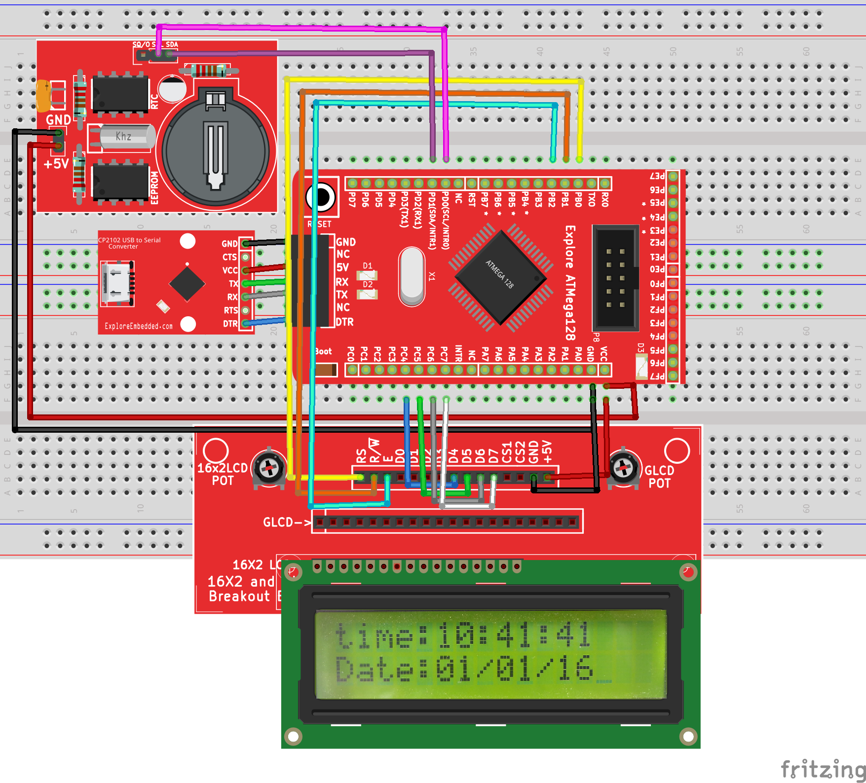
In this example we are using DS1307 serial Real Time Clock. DS1307 which communicate with Atmega128 through I2C ( Inter-Integrated-Circuit) protocol. Befor we continue please refer the Basics of Real Time Clock with AVR. In RTC Breakout SCL and SDA pins are broken out which are needs to be connected to Atmega128 controller I2C lines. LCD data lines (Lower 4 bit D4 to D7) are connected to Port B4 to Port B7 of Atmega128, and similarly LCD control lines(RS,R/W and Enable) are connected to Port B0 to Port B2 of Atmega128.
Hook Up
Code
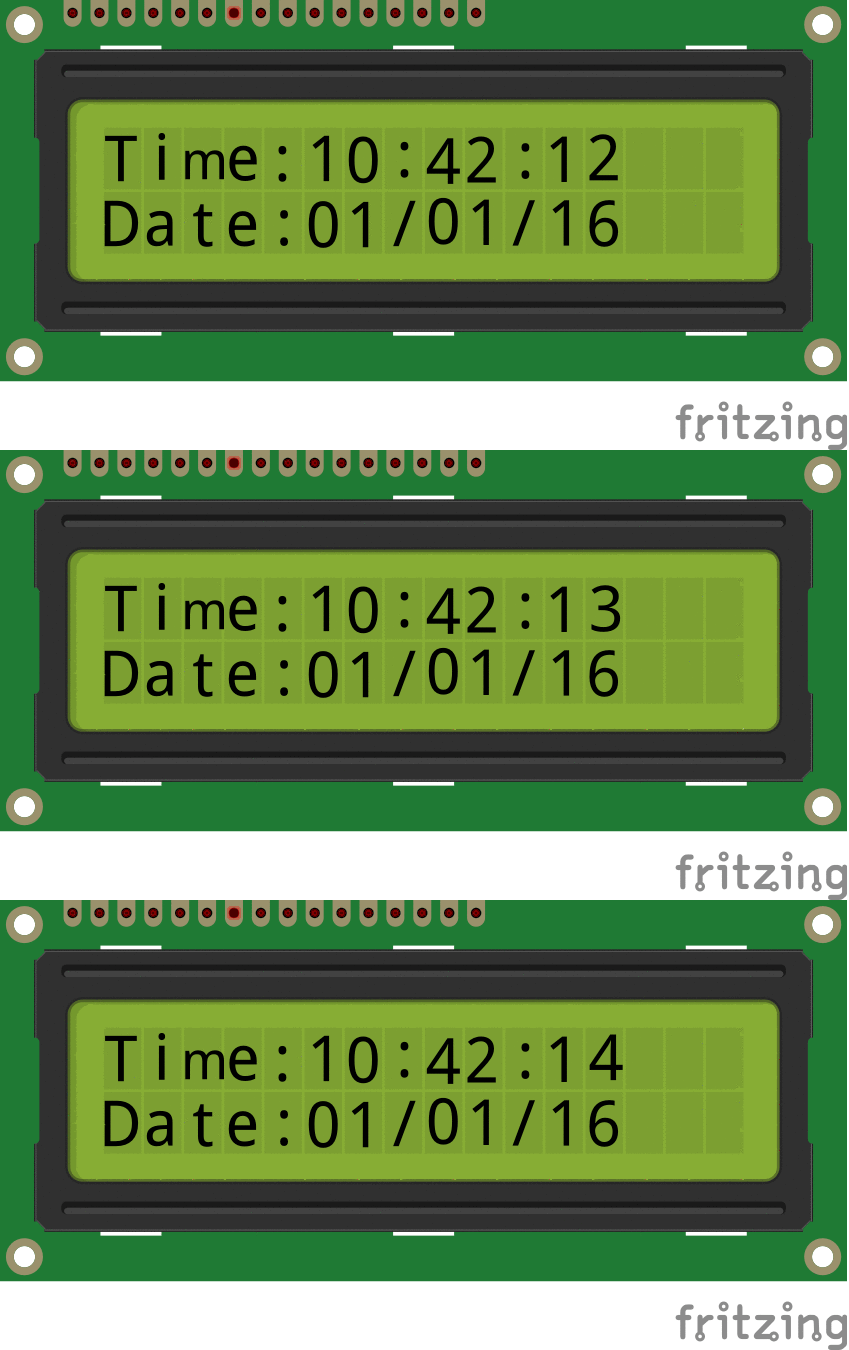
Demo
Video Tutorial
For those of you, who would like to watch instead of read we have made a video with all the gyan.
Downloads
Download the complete project folder from the below link:
https://github.com/ExploreEmbedded/ATMega-128-Break-Out-BoardDVB-12007/archive/master.zip
Have a opinion, suggestion , question or feedback about the article let it out here!


