Basics of I2C with AVR
Contents
Basics
The I²C (Inter-Integrated Circuit) protocol, referred to as I-squared-C, I-two-C, or IIC) is two wire serial communication protocol for connecting low speed peripherals to a micrcontroller or computer motherboard.
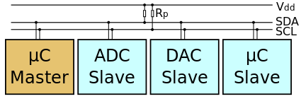
The I²C simply require only two wires for communication. One is called the Serial Data (SDA) and the other is Serial Clock (SCL) as shown.
There are various modes and configurations in which it can be used. Let us start simply with a single master and a single slave.
The Master generates the clock for serial communication(SCL). A stream of data bits(B1 to BN) is transferred between the start and the stop bits.
I2C Timings and Conditions.
Figure below shows the timing diagram for I²C.

Start Condition(S)
As seen from the timing diagram, a data transfer is initiated with the Start(S) condition. The start occurs when SCL is high and SDA goes from high to low.
Data bits transfer(B1...Bn)
A bit is transmitted at every high level of the clock (SCL) after the start condition. As shown in the image bits B1 to Bn are transmitted at high level of every successive clock cycles.
Stop bit (P)
To stop the data transfer, the clock(SCL) is held high, while data(SDA) goes from low to high.
AVR Atmega32 I2C Registers
TWBR ( TWI Bit Rate Register )
| TWBR | |||||||
|---|---|---|---|---|---|---|---|
| 7 | 6 | 5 | 4 | 3 | 2 | 1 | 0 |
| TWBR7 | TWBR6 | TWBR5 | TWBR4 | TWBR3 | TWBR2 | TWBR1 | TWBR0 |
Bits [7:0] – Bit Rate
It selects the division factor for the bit rate generator. The bit rate generator is basically a frequency divider. It generates the SCL clock frequency in the Master modes.
TWCR ( TWI Control Register )
It is used to control all TWI operations.
| TWCR | |||||||
|---|---|---|---|---|---|---|---|
| 7 | 6 | 5 | 4 | 3 | 2 | 1 | 0 |
| TWBR7 | TWBR6 | TWBR5 | TWBR4 | TWBR3 | TWBR2 | TWBR1 | TWBR0 |
• Bit 7 – TWINT: TWI Interrupt Flag
This bit is set by hardware when the TWI has finished its current job and expects application software response. It is not automatically cleared by hardware when executing the interrupt routine. So, you must clear TWINT Flag by writing a logic one to it.
Also note that clearing this flag starts the operation of the TWI. So before clearing this flag, all accesses to the other TWI registers must be complete .
• Bit 6 – TWEA: TWI Enable Acknowledge Bit
It controls the generation of the acknowledge pulse.
If the TWEA bit is written to one, the ACK pulse is generated on the TWI bus if the following conditions are met:
1. The device’s own slave address has been received.
2. A general call has been received, while the TWGCE bit in the TWAR is set.
3. A data byte has been received in Master Receiver or Slave Receiver mode.
You can virtually disconnect device from the Two-wire Serial Bus temporarily by writting zero to TWEA. And to resume address recognition write one to it.
• Bit 5 – TWSTA: TWI START Condition Bit
To make the micro-controller master device on the Two wire Serial Bus, you must set this bit.
• Bit 4 – TWSTO: TWI STOP Condition Bit
In Master mode, write the one TWSTO bit to generate a STOP condition. This bit is cleared automatically when the STOP condition is executed on the bus.
In slave mode, setting the TWSTO bit can be used to recover from an error condition.
• Bit 3 – TWWC: TWI Write Collision Flag
The TWWC bit is set when attempting to write to the TWI Data Register – TWDR when TWINT is low. This flag is cleared by writing the TWDR Register when TWINT is high.
• Bit 2 – TWEN: TWI Enable Bit
To start TWI interface write one to this bit.
• Bit 1 – Reserved Bit
This bit is a reserved bit and will always read as zero.
• Bit 0 – TWIE: TWI Interrupt Enable
When this bit is written to one, and the I-bit in SREG is set, the TWI interrupt request will be activated for as long as the TWINT Flag is high.
TWSR ( TWI Status Register )
| TWCR | |||||||
|---|---|---|---|---|---|---|---|
| 7 | 6 | 5 | 4 | 3 | 2 | 1 | 0 |
| TWS7 | TWS6 | TWS5 | TWS4 | TWS3 | - | TWPS1 | TWPS0 |
• Bits [7:3] – TWS: TWI Status
These five bits reflect the status of the TWI logic and the Two-wire Serial Bus.
• Bit 2 – Reserved Bit
This bit is reserved and will always read as zero.
• Bits [1:0] – TWPS: TWI Prescaler Bits
These bits can be read and written, and control the bit rate prescaler
| TWPS1 | TWPS0 | Prescaler Value |
|---|---|---|
| 0 | 0 | 1 |
| 0 | 1 | 4 |
| 1 | 0 | 16 |
| 1 | 1 | 64 |
TWDR ( TWI Data Register )
In Transmit mode, This register contains the next byte to be transmitted in transmission mode and in case of receive mode it has last byte received. Note that, it is writable only when the TWI is not in the process of shifting a byte.
| TWDR | |||||||
|---|---|---|---|---|---|---|---|
| 7 | 6 | 5 | 4 | 3 | 2 | 1 | 0 |
| TWD7 | TWD6 | TWD5 | TWD4 | TWD3 | TWDD2 | TWD1 | TWD0 |

