A6b:8051 Interfacing: EEPROM AT24C16
Video Tutorial
Intro
In this tutorial we will interface the EEPROM IC 'AT24C16' with 8051. AT24C16 works on I2C protocol, hence it is recommended to go through the I2C/TWI Basics tutorial first. AT24C16 has 16K bits of EEPROM Memory. This can be quite useful when your project needs some kind of permanent storage in real time. Say, you want to read some sensor, keep count, time and want these values to be stored, and retrieve them even if the unit is turned off and turn ON back again! You need an EEPROM then, because 8051 does not have on built in! <br\>
Schematic
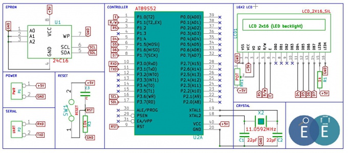
The schematic is pretty simple, you could connect the I2C lines to any of the two 8051 port pins, because the 8051 does not have in built hardware to handle I2C communication, we need to 'bit-bang' it. For this tutorial we have made connections as shown in the image below, also notice the character LCD in 4 bit mode. So what we do in this tutorial is write some strings to the EEPROM and read them back.
The AT24C16
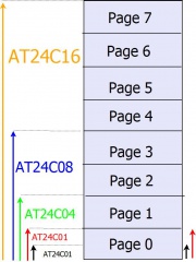
The AT24C16 is one variant of AT24C series others are AT24C01, AT24C02,AT24C04,AT24C08, the tutorial should hold good for all of these. Table below show memory arrangement for all of these
| IC | Memory Size | Page Numbers |
|---|---|---|
| AT24C01 | 1K Bits(128 Bytes) | 0 |
| AT24C02 | 2K Bits(256 Bytes) | 0 |
| AT24C04 | 4K Bits(512 Bytes) | 0 to 1 |
| AT24C08 | 8K Bits(1024 Bytes) | 0 to 3 |
| AT24C16 | 16K Bits(2048 Bytes) | 0 to 7 |
Note the following from the memory map.
- Each page requires 8-bits to to access the 256 locations
- Additional 3 bits are required to address 8 pages
- Hence 13 bits are required to address the entire 16K Memory.
When using I2C, we send the device ID first and then the Memory address. Now, if looking at the table below, you could observe the following.
- The first four bits of the Device ID are same for all the ICs '1010
- If the next three bits are A2,A1,A0; these are physical pins on the device, which means if multiple ICs can be connected to I2C bus, however if you calculate for all ICs, the max effective memory will only be 16 K bits.
- If the next there bits are P2,P1,P0; they define the page numbers.
| IC | Device ID | |||||||
|---|---|---|---|---|---|---|---|---|
| AT24C01 | 1 | 0 | 1 | 0 | A2 | A1 | A0 | R/W |
| AT24C02 | 1 | 0 | 1 | 0 | A2 | A1 | A0 | R/W |
| AT24C04 | 1 | 0 | 1 | 0 | A2 | A1 | P0 | R/W |
| AT24C08 | 1 | 0 | 1 | 0 | A2 | P1 | P0 | R/W |
| AT24C16 | 1 | 0 | 1 | 0 | P2 | P1 | P0 | R/W |
Code
Since we are using AT24C16 for the demo, we will write a program to write strings to starting locations of all of the 8 pages. The main.c code is shown below, the complete code can be downloaded at the end.
/* Reg51.h contains the defnition of all ports and SFRs */
#include <reg51.h>
#include <delay.h>
#include "lcd.h" //User defined LCD library which conatins the lcd routines
#include "eeprom.h" //User defined library which conatins eeprom(At2404) routines
unsigned char cnt;
/* start the main program */
void main()
{
unsigned char eeprom_address=0x00, write_String[] = {"hello world"}, read_string[15];
/* Initilize the lcd before displaying any thing on the lcd */
LCD_Init();
LCD_GoToLineOne();      // Move the cursor to first line
LCD_DisplayString("EEPROM AT24C16");
EEPROM_WriteString(eeprom_address,"P0:hello",0);
EEPROM_WriteString(eeprom_address,"P1:hi",1);
EEPROM_WriteString(eeprom_address,"P2:good",2);
EEPROM_WriteString(eeprom_address,"P3:morning",3);
EEPROM_WriteString(eeprom_address,"P4:how",4);
EEPROM_WriteString(eeprom_address,"P5:is",5);
EEPROM_WriteString(eeprom_address,"P6:your",6);
EEPROM_WriteString(eeprom_address,"P7:day?",7);
  for(cnt =0; cnt<8; cnt++)
  {
  LCD_GoToLineTwo();       // Move the cursor to Second line
  LCD_DisplayString("               ");
  LCD_GoToLineTwo();
  LCD_DisplayString("Rd:"); //Display the message on Second line
  EEPROM_ReadString(eeprom_address,read_string,cnt);
  LCD_DisplayString(read_string);//Display the read String
  delay_sec(2);
  }
    while(1);
}


