
I2C/TWI Basics
Contents
[hide]Video Tutorial
Introduction
The I²C (Inter-Integrated Circuit) protocol, referred to as I-squared-C, I-two-C, or IIC) is two wire serial communication protocol for connecting low speed peripherals to a micrcontroller or computer motherboard.

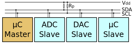
The I²C simply require only two wires for communication. One is called the Serial Data (SDA) and the other is Serial Clock (SCL) as shown.
There are various modes and configurations in which it can be used. Let us start simply with a single master and a single slave.
The Master generates the clock for serial communication(SCL). A stream of data bits(B1 to BN) is transferred between the start and the stop bits.
I2C Timings and Conditions.
Figure below shows the timing diagram for I²C.
Start Condition(S)
As seen from the timing diagram, a data transfer is initiated with the Start(S) condition. The start occurs when SCL is high and SDA goes from high to low.
Data bits transfer(B1...Bn)
A bit is transmitted at every high level of the clock (SCL) after the start condition. As shown in the image bits B1 to Bn are transmitted at high level of every successive clock cycles.
Stop bit (P)
To stop the data transfer, the clock(SCL) is held high, while data(SDA) goes from low to high.
Interfacing Microcontroller to I2C devices
Usually, following procedure is used to communicate with the peripherals.
- Master initializes the communication by sending the slave address on the bus.
- Master reads or writes data or commands from and to the slaves depending on the interfaced devices.
We will see practical implementation of I2C on different peripherals and Micrcontrollers. The examples will be updated here.
Practical Examples
Have a opinion, suggestion or feedback about this article, let it out here!

Graphics LCD Basics : KS0108 based JHD12864E
In this tutorial we will look at interfacing KS0108 display controller based JHD12864E display. There are many displays out there based on KS0108 or compatible display controller. They all work...
LCD 16 x 2 Basics
Video Tutorial Introduction:LCD Liquid Crystal Display(LCDs) provide a cost effective way to put a text output unit for a microcontroller. As we have seen in the previous tutorial...