Difference between revisions of "Interfacing Seven Segment with 8051"
| (15 intermediate revisions by 3 users not shown) | |||
| Line 1: | Line 1: | ||
[[Category:8051 tutorials]] | [[Category:8051 tutorials]] | ||
| − | + | In the earlier tutorials, we saw how to interface the LEDs to PIC microcontroller and wrote the code to blink them. However, the LEDs cannot be used to display any user information like numbers, chars etc. To display numeric values we can use seven segment displays. First, we will interface a seven segment to 8051 and display a single digit decimal counter(0-9). | |
| + | Later same will be extended to multiplex 4 seven segment displays to generate a 4-digit counter. | ||
| + | <br><br><br> | ||
| − | [[File: | + | =Seven Segment Display= |
| − | ''' | + | [[File:BasicSevenSegmentDisplay.png|thumbnail|Basic 7 segment Display]] |
| + | Well, the name 7 segments imply there are 7 LED segments arranged as shown in figure 1. | ||
| + | After LEDs, these are the easiest interfaces to a microcontroller. | ||
| + | There is also a decimal point or dp. It is used when decimal digits like 5.1 etc are displayed. | ||
| + | ==Applications== | ||
| + | Seven segments are widely used in applications where digits[0-9] are required to be displayed.Although they also display letters A to F as shown in figure(2) simulation. | ||
| + | This is a very simple and convenient way to display numbers in a bright fashion. | ||
| + | ==Form Factor== | ||
| + | |||
| + | *'''Sizes''':They come in various sizes; 0.28”, 0.3”, 0.32”, 0.36”, 0.39”, 0.4”, 0.5”, 0.56”, 0.6”, 0.8”, 1.0”, 1.2”, 1.5”, 1.8”, 2.0”, 2.3”, 3.0”, 4.0”, 5.0”, 7.0”) | ||
| + | *'''Colors''': and varied colors too; Red, Green, Yellow, Orange, Blue, and White. | ||
| + | <br><br> | ||
| + | |||
| + | |||
| + | =Working= | ||
| + | Since these are basically LEDs arranged as a group they can either have the anode in common or cathode thus they are named as Common-Anode/Common-Cathode displays. | ||
| + | [[File:Common Cathode 7Segment.jpeg|thumbnail]] | ||
| + | [[File:Common Anode 7Segment.jpeg|thumbnail]] | ||
| + | |||
| + | *<b>Common Cathode</b>: In this type of segments all the cathode terminals are made common and tied to GND. Thus the segments '''a''' to '''g''' needs a logic High signal(5v) in order to glow. <br><br> | ||
| + | *<b>Common Anode</b>: In this type of segments all the anodes terminals are made common and tied to VCC(5v). Thus the segments '''a''' to '''g''' needs a logic LOW signal(GND) in order to glow.<br> | ||
| + | <br><br><br><br> | ||
| + | |||
| + | [[FILE:0SevenSegment.gif]] | ||
| + | |||
| + | Below table shows the binary/hex values for displaying the digits on CommonAnode seven segment display. | ||
| + | {| class="table table-striped table-hover table-condensed table-bordered" | ||
| + | |-class="info" | ||
| + | |Digit || h || g || f || e || d || c || b || a || Hex Value | ||
| + | |- | ||
| + | |0 || 1 || 1 || 0 || 0 || 0 || 0 || 0 || 0 || 0xC0 | ||
| + | |- | ||
| + | |1 || 1 || 1 || 1 || 1 || 1 || 0 || 0 || 1 || 0xF9 | ||
| + | |- | ||
| + | |2 || 1 || 0 || 1 || 0 || 0 || 1 || 0 || 0 || 0xA4 | ||
| + | |- | ||
| + | |3 || 1 || 0 || 1 || 1 || 0 || 0 || 0 || 0 || 0xB0 | ||
| + | |- | ||
| + | |4 || 1 || 0 || 0 || 1 || 1 || 0 || 0 || 1 || 0x99 | ||
| + | |- | ||
| + | |5 || 1 || 0 || 0 || 1 || 0 || 0 || 1 || 0 || 0x92 | ||
| + | |- | ||
| + | |6 || 1 || 0 || 0 || 0 || 0 || 0 || 1 || 0 || 0x82 | ||
| + | |- | ||
| + | |7 || 1 || 1 || 1 || 1 || 1 || 0 || 0 || 0 || 0xF8 | ||
| + | |- | ||
| + | |8 || 1 || 0 || 0 || 0 || 0 || 0 || 0 || 0 || 0x80 | ||
| + | |- | ||
| + | |9 || 1 || 0 || 0 || 1 || 0 || 0 || 0 || 0 || 0x90 | ||
| + | |} | ||
| + | <br><br> | ||
| + | |||
| + | =Hardware Connection= | ||
| + | Below image shows the hardware connection as per the table.<br> | ||
| + | {| class="table table-striped table-hover table-condensed table-bordered" | ||
| + | |-class="info" | ||
| + | !a || b || c || d || e || f || g || h || COM/S1 | ||
| + | |- | ||
| + | |P2.0 || P2.1 || P2.2 || P2.3 || P2.4 || P2.5 || P2.6 || P2.7 || VCC | ||
| + | |} | ||
| + | [[File:8051 SingleSegmant.png]] | ||
| + | |||
| + | =Code: Single Segment= | ||
| + | Below is the sample code to display single digit up counter. | ||
| + | <html> | ||
| + | <script src="https://gist.github.com/SaheblalBagwan/efc062c8c676a9a3575b9de450debaed.js"></script> | ||
| + | </html> | ||
| + | |||
| + | <br><br> | ||
| + | |||
| + | =Hardware Connections= | ||
| + | [[File:SevenSegmentTest.png]] | ||
| + | |||
| + | =Code: Four Segments= | ||
| + | Below is the sample code for multiplexing four segments to display 4-digit up counter. | ||
| + | <html> | ||
| + | <script src="https://gist.github.com/SaheblalBagwan/816e5c73e37dfa2fe8d8fba640ab6b9a.js"></script> | ||
| + | </html> | ||
| + | |||
| + | =Downloads= | ||
| + | Download the sample code and design files from [https://github.com/ExploreEmbedded/8051_DevelopmentBoard this link]. | ||
| + | |||
| + | |||
| + | Have an opinion, suggestion , question or feedback about the article let it out here! | ||
| + | {{DISQUS}} | ||
Latest revision as of 10:16, 2 September 2016
In the earlier tutorials, we saw how to interface the LEDs to PIC microcontroller and wrote the code to blink them. However, the LEDs cannot be used to display any user information like numbers, chars etc. To display numeric values we can use seven segment displays. First, we will interface a seven segment to 8051 and display a single digit decimal counter(0-9).
Later same will be extended to multiplex 4 seven segment displays to generate a 4-digit counter.
Contents
Seven Segment Display
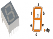
Well, the name 7 segments imply there are 7 LED segments arranged as shown in figure 1. After LEDs, these are the easiest interfaces to a microcontroller. There is also a decimal point or dp. It is used when decimal digits like 5.1 etc are displayed.
Applications
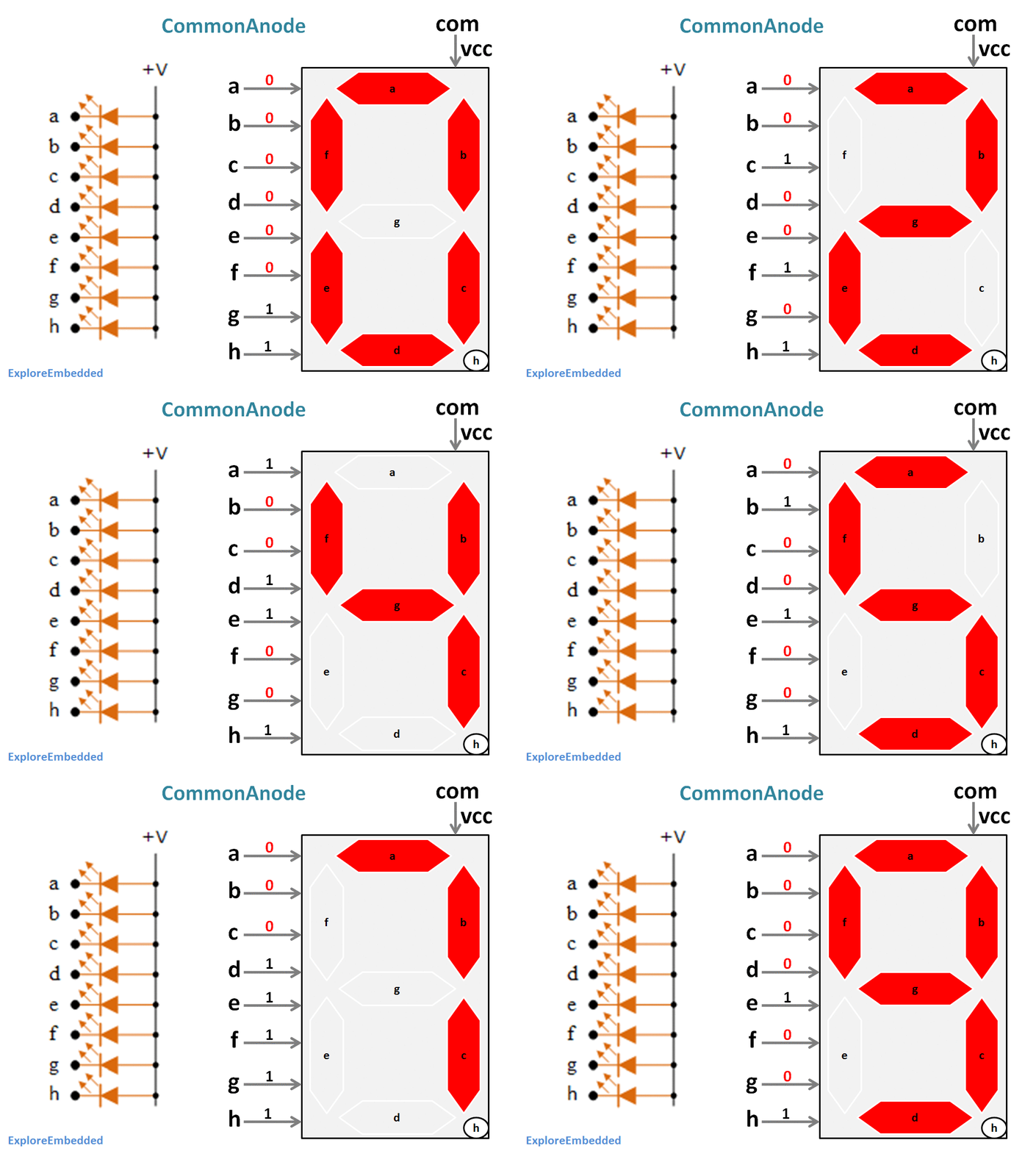
Seven segments are widely used in applications where digits[0-9] are required to be displayed.Although they also display letters A to F as shown in figure(2) simulation. This is a very simple and convenient way to display numbers in a bright fashion.
Form Factor
- Sizes:They come in various sizes; 0.28”, 0.3”, 0.32”, 0.36”, 0.39”, 0.4”, 0.5”, 0.56”, 0.6”, 0.8”, 1.0”, 1.2”, 1.5”, 1.8”, 2.0”, 2.3”, 3.0”, 4.0”, 5.0”, 7.0”)
- Colors: and varied colors too; Red, Green, Yellow, Orange, Blue, and White.
Working
Since these are basically LEDs arranged as a group they can either have the anode in common or cathode thus they are named as Common-Anode/Common-Cathode displays.
- Common Cathode: In this type of segments all the cathode terminals are made common and tied to GND. Thus the segments a to g needs a logic High signal(5v) in order to glow.
- Common Anode: In this type of segments all the anodes terminals are made common and tied to VCC(5v). Thus the segments a to g needs a logic LOW signal(GND) in order to glow.
Below table shows the binary/hex values for displaying the digits on CommonAnode seven segment display.
| Digit | h | g | f | e | d | c | b | a | Hex Value |
| 0 | 1 | 1 | 0 | 0 | 0 | 0 | 0 | 0 | 0xC0 |
| 1 | 1 | 1 | 1 | 1 | 1 | 0 | 0 | 1 | 0xF9 |
| 2 | 1 | 0 | 1 | 0 | 0 | 1 | 0 | 0 | 0xA4 |
| 3 | 1 | 0 | 1 | 1 | 0 | 0 | 0 | 0 | 0xB0 |
| 4 | 1 | 0 | 0 | 1 | 1 | 0 | 0 | 1 | 0x99 |
| 5 | 1 | 0 | 0 | 1 | 0 | 0 | 1 | 0 | 0x92 |
| 6 | 1 | 0 | 0 | 0 | 0 | 0 | 1 | 0 | 0x82 |
| 7 | 1 | 1 | 1 | 1 | 1 | 0 | 0 | 0 | 0xF8 |
| 8 | 1 | 0 | 0 | 0 | 0 | 0 | 0 | 0 | 0x80 |
| 9 | 1 | 0 | 0 | 1 | 0 | 0 | 0 | 0 | 0x90 |
Hardware Connection
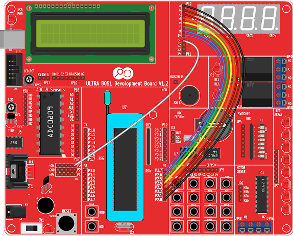
Below image shows the hardware connection as per the table.
| a | b | c | d | e | f | g | h | COM/S1 |
|---|---|---|---|---|---|---|---|---|
| P2.0 | P2.1 | P2.2 | P2.3 | P2.4 | P2.5 | P2.6 | P2.7 | VCC |
Code: Single Segment
Below is the sample code to display single digit up counter.
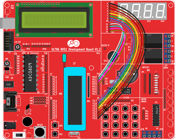
Hardware Connections
Code: Four Segments
Below is the sample code for multiplexing four segments to display 4-digit up counter.
Downloads
Download the sample code and design files from this link.
Have an opinion, suggestion , question or feedback about the article let it out here!


