
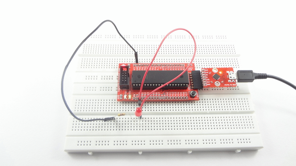
Switch and a LED with AVR Breakout
Now we will control the LED depending on external input. In this tutorial we will interface a switch to one of the port pin and display its status on LED connected to other port.
Basics
For this tutorial we will a connect a switch to PORT C0 and LED to PORT B0 of Atmega32. W will configure PORT A0 as input to read the switch status and PORT C0 as outputto display the switch status on LED. Initially LED will be ON , when we press switch the LED will be OFF.
Refer the AVR I/O Register Configuration tutorial for basics of GPIO register configuration.
Hook Up

Code
| #include <avr/io.h> | |
| #define LED 0 | |
| #define SWITCH 0 | |
| int main(void) | |
| { | |
| DDRB |= (1<<LED); // Configure PORTB as output to connect Led | |
| DDRC &= ~(1<<SWITCH); // Configure PORTC as input to connect switch | |
| PORTC |= 0x01; // Enable The PullUps of PORTC. | |
| while(1) | |
| { | |
| if(!PINC) | |
| PORTB &= ~(1<<LED); | |
| else | |
| PORTB |= (1<<LED); | |
| } | |
| return 0; | |
| } |
Demo

Downloads
Download the complete project folder from the below link:
https://github.com/ExploreEmbedded/AVR-MCU-Breakout-Board/archive/master.zip
Have a opinion, suggestion , question or feedback about the article let it out here!
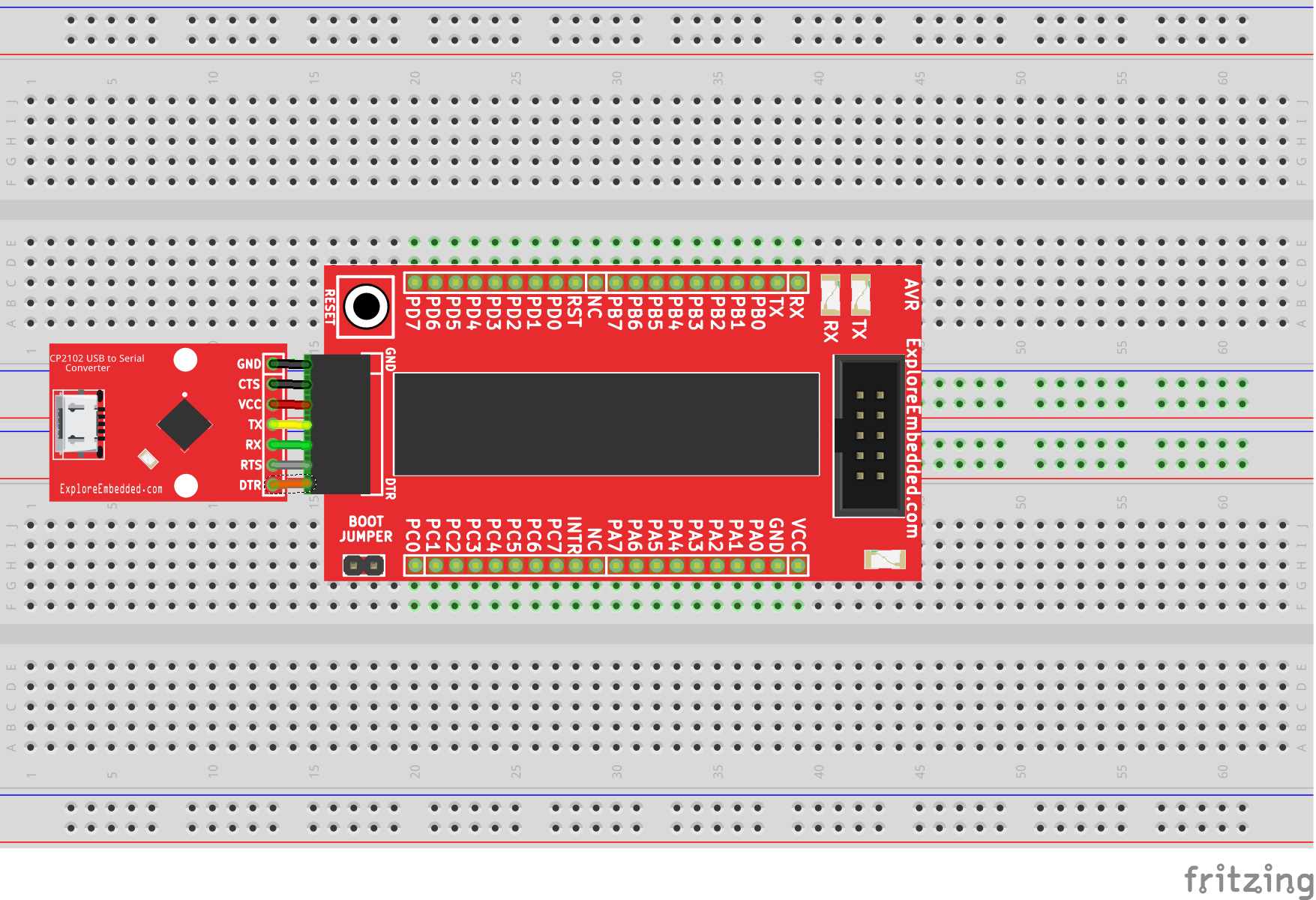
Setting Up AVR Breakout
In this tutorial we will look at the basic setup required to get started with AVR breakout board. After completion of this basic setup we can interface peripherals with the breakout board. ...
Blinky with AVR Breakout
In this tutorial we will get hands on with AVR breakout board. Here we will interface simple LED with one of the port pins. For this tutorial we will require a breadboard, LEDs and resistors. ...
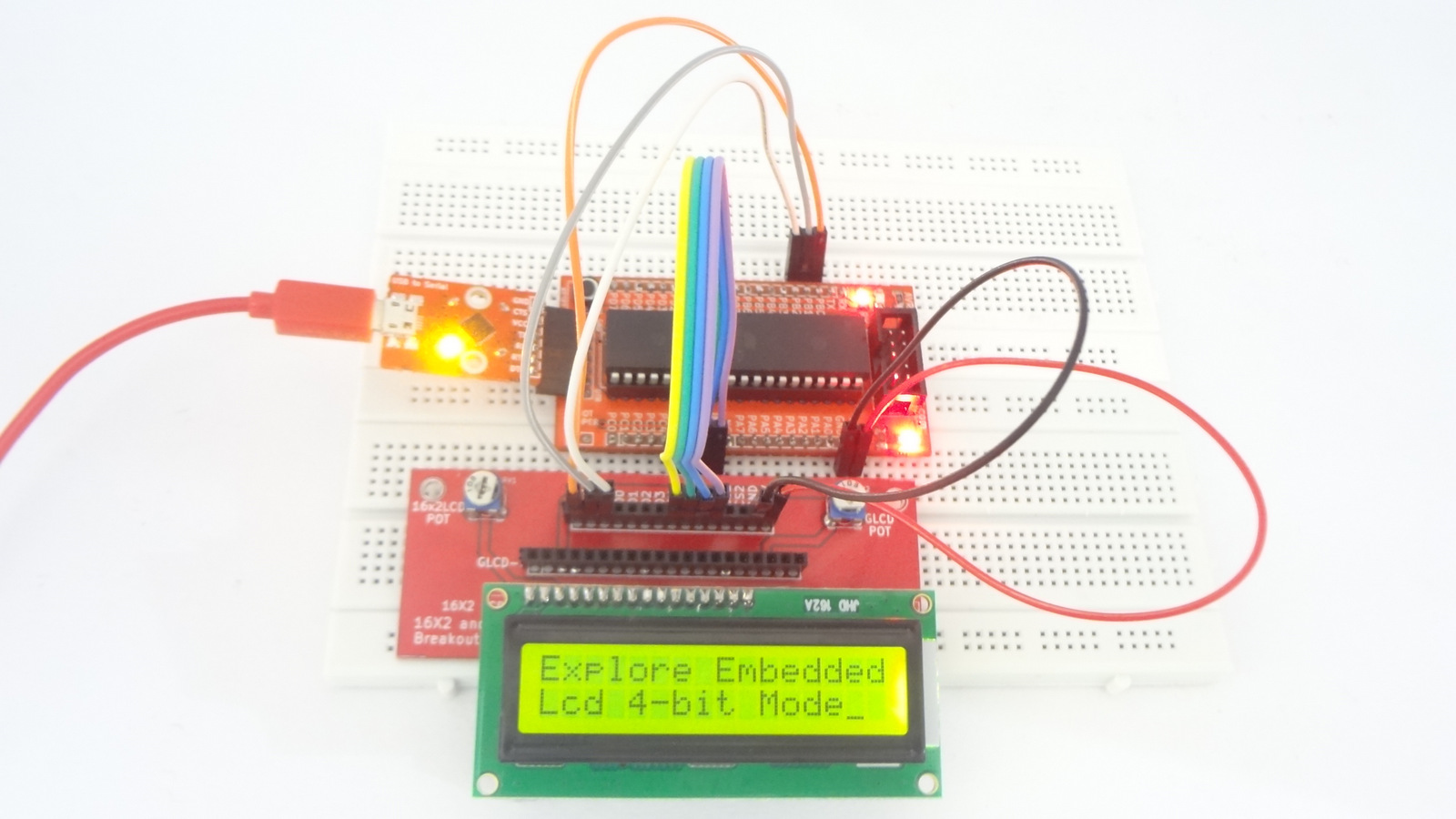
Interfacing LCDs with AVR Breakout
In this tutorial let's interface a 16x1,16x2 and 20x4 character display with AVR breakout board. For this tutorial we will require a LCD Breakout. Basics LCD can be interfaced with...
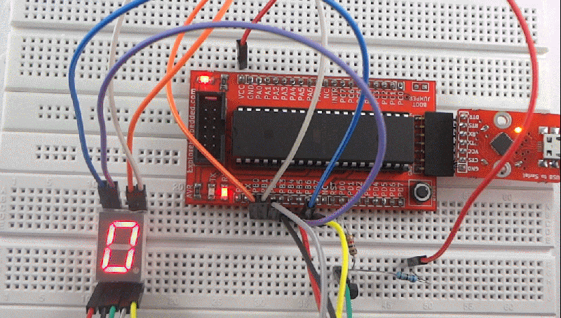
Interfacing Seven Segment Display with AVR Breakout
After blinking the LED , Let's display user information like numeric value using seven segment display. In this tutorial we will interface a seven segment display to AVR breakout board and display a...